
A Dynamic Numerical Simulation Method of Air Leakage Flow Field in Goaf Based on Deformed Geometry

A kind of numerical simulation, goaf technology, applied in CAD numerical modeling, electrical digital data processing, special data processing applications, etc., can solve the problems of technical and theoretical difficulty in popularization and application, unable to realize the dynamic change of goaf, etc.

Active Publication Date: 2019-03-12
LIAONING TECHNICAL UNIVERSITY
View PDF3 Cites 0 Cited by
  • Summary
  • Abstract
  • Description
  • Claims
  • Application Information

AI Technical Summary

Problems solved by technology

The commonly used methods for calculating and simulating the stope wind flow field earlier mainly include the self-programmed stope flow field calculation method based on FORTRAN language in the 1980s and 1990s, and the G3 software simulation method and dual-coordinate system simulation method since the 21st century. method, moving coordinate system method, and common commercial software PHOENICS, fluent, comsol and other methods. The above methods have improved the theoretical calculation level of stope flow field to a certain extent for the simulation calculation of goaf flow field. Safety production provides guidance, but some of these methods cannot realize the dynamic changes of the goaf during the advancing process of the working face, and some of them are based on self-programmed development. The technical and theoretical difficulties are relatively difficult, which has certain limitations in the promotion and application of this industry

Method used


Image

  • A Dynamic Numerical Simulation Method of Air Leakage Flow Field in Goaf Based on Deformed Geometry
  • A Dynamic Numerical Simulation Method of Air Leakage Flow Field in Goaf Based on Deformed Geometry
  • A Dynamic Numerical Simulation Method of Air Leakage Flow Field in Goaf Based on Deformed Geometry

Examples


Embodiment Construction

[0031] The specific implementation manners of the present invention will be described in detail below in conjunction with the accompanying drawings.

[0032] A dynamic numerical simulation method for air leakage flow field in gobs based on deformed geometry, including:

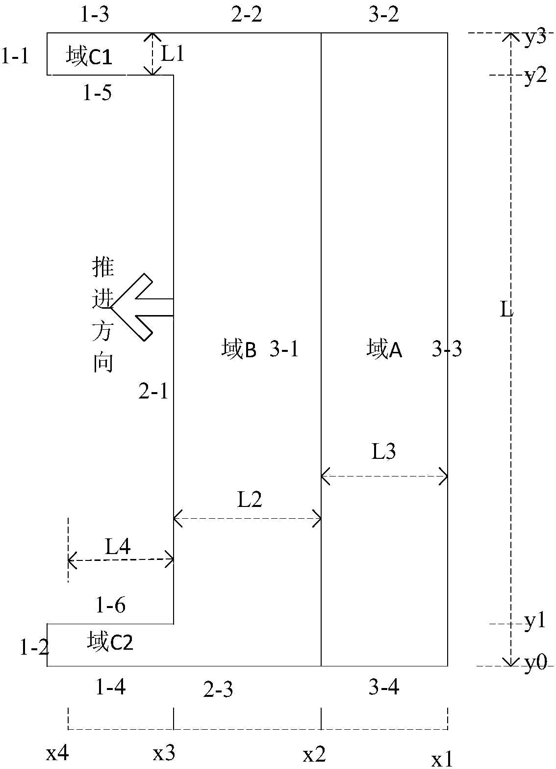
[0033] Step 1. Based on the goaf formed after one day of mining at the average daily advance speed, establish the initial goaf geometric model for coal mining face mining: take the daily average advance speed as the increase rate of the goaf length, and based on the deformation Geometry control The geometric model of the gob is extended with the back mining of the coal mining face, and the air inlet and return air lanes of the coal mining face are set;

[0034] In this embodiment, the initial goaf geometric model is as follows figure 1 As shown, the coal mining face is 90m long, the air inlet and return roadway is 3.5m wide, 4m high, and the mining hole is about 7m wide, that is, the maximum distance between ...


PUM


Abstract

The invention provides a method for dynamic numerical simulation of air leakage flow field in a goaf based on deformation geometry, which includes: establishing an initial goaf for mining in a coal mining face according to the goaf formed after mining at a daily average advance speed for one day Geometric model; set the free deformation area, fixed boundary, and moving boundary of the goaf; set the air leakage flow field of the goaf; divide the initial geometric model of the goaf into grids and carry out numerical simulation calculation of the air leakage field of the goaf; The average advance speed gradually advances the geometric model of the goaf and re-subdivides the grid and carries out the numerical simulation calculation of the air leakage field in the goaf until it advances to the stop production line or does not reach the stop production line but reaches the set stop calculation time. This method uses deformation geometry to control the dynamic evolution process of coal mining face and goaf boundary movement and regional change, and uses free and porous medium fluid flow to control the flow field of the working face and goaf. The coupling calculation of the two describes the goaf Dynamic changes and distribution rules of air leakage flow field.

Description

technical field [0001] The invention relates to the technical field of goaf air leakage simulation, in particular to a dynamic numerical simulation method for goaf air leakage flow field based on deformation geometry. Background technique [0002] Air leakage in the goaf is an important factor affecting the safe mining of the working face. The air leakage leads to the spontaneous combustion of the residual coal in the goaf and induces a large amount of toxic and harmful gases in the goaf to pour out to the working face. Provide theoretical basis and technical support. The commonly used methods for calculating and simulating the stope wind flow field earlier mainly include the self-programmed stope flow field calculation method based on FORTRAN language in the 1980s and 1990s, and the G3 software simulation method and dual-coordinate system simulation method since the 21st century. method, moving coordinate system method, and common commercial software PHOENICS, fluent, coms...

Claims


Application Information

Patent Timeline
Patent Type & Authority Patents(China)
IPC IPC(8): G06F17/50
CPCG06F30/367G06F2111/10
Inventor 齐庆杰董子文王欢于文惠李兴华秦凯
Owner LIAONING TECHNICAL UNIVERSITY
Learn More