
Communication device and electronic device

A communication device and sub-range technology, which is applied in the directions of antenna supports/installation devices, circuits, electrical components, etc., to achieve the effect of suppressing harmonic interference

Active Publication Date: 2016-08-17
MEDIATEK INC
View PDF3 Cites 1 Cited by
  • Summary
  • Abstract
  • Description
  • Claims
  • Application Information

AI Technical Summary

Problems solved by technology

[0003] However, the technique of carrier aggregation requires multiple frequency bands or sub-ranges and wide frequency bandwidth
Designing such antenna systems to meet the demands of carrier aggregation has become a serious challenge for engineers

Method used


Image

  • Communication device and electronic device
  • Communication device and electronic device
  • Communication device and electronic device

Examples


Embodiment Construction

[0023] In order to illustrate the purpose, features and advantages of the present invention, the embodiments and drawings of the present invention will be described in detail later.

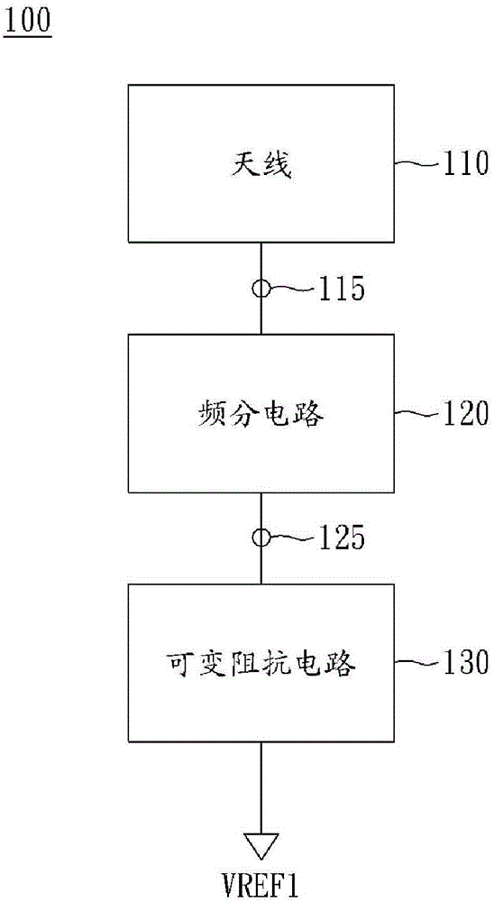
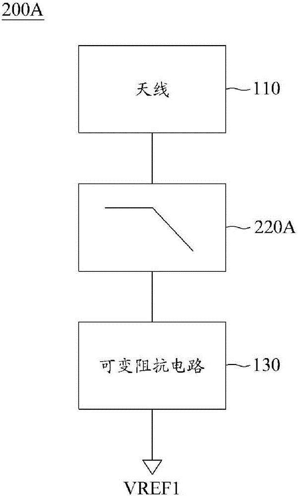
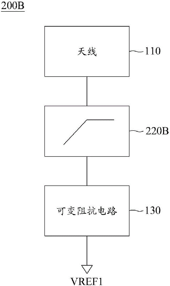
[0024] figure 1 is a schematic diagram of a communication device 100 according to an embodiment of the present invention. For example, the communication device 100 can be a smart phone, a tablet computer or a notebook computer. The communication device 100 may support carrier aggregation technology in the LTE-A field. Such as figure 1 As shown in , the communication device 100 includes an antenna 110 , a frequency division circuit 120 and at least one variable impedance circuit (variable impedance circuit) 130 . The frequency division circuit 120 has a common port 115 coupled to the antenna 110 and at least one output port 125 , each of the at least one output port is coupled to one of the at least one variable impedance circuit 130 . More specifically, in figure 1 In one embodiment, an outp...


PUM


Abstract

The invention is directed to a communication device and an electronic device. The communication device includes an antenna, a frequency dividing circuit, and at least one variable impedance circuit. The frequency dividing circuit has a common port coupled to the antenna and at least one output port. The frequency dividing circuit is configured to divide a frequency range received from the common port into a plurality of frequency sub-ranges and output at least one of the frequency sub-ranges respectively at the at least one output port. Each variable impedance circuit is coupled between a corresponding one of the at least one output port of the frequency dividing circuit and a respective first reference voltage. Each variable impedance circuit provides a respective variable impedance value switched between different respective impedance values. The communication device is advantageous in that harmonic interference in the communication device can be effectively eliminated.

Description

technical field [0001] The present invention relates to communication devices, and more particularly, to communication devices that can support communication in multiple frequency sub-ranges or carrier aggregation domains. Background technique [0002] To meet Long Term Evolution-Advanced (LTE-A) requirements, it is necessary to support a transmission bandwidth wider than 20 MHz specified in 3GPP Release 8 / 9. For this, the preferred solution is carrier aggregation, which is one of the most prominent features of 4G LTE-A. Carrier aggregation allows extending the effective bandwidth of transmissions to user terminals through the parallel use of radio resources across multiple carriers. Multiple component carriers are aggregated to form a larger overall transmission bandwidth. [0003] However, the technique of carrier aggregation requires multiple frequency bands or sub-ranges and a wide frequency bandwidth. Designing such antenna systems to meet the demands of carrier aggr...

Claims


Application Information

Patent Timeline
Patent Type & Authority Applications(China)
IPC IPC(8): H04B1/00H01Q1/24
CPCH01Q1/241H04B1/0057H04B15/06
Inventor 戴祯坊洪崇育康庭维
Owner MEDIATEK INC
Learn More