Charge pump timing control
A charge pump and controller technology, applied in control/regulating systems, electrical components, regulating electrical variables, etc., to achieve the effect of high-efficiency power conversion
- Summary
- Abstract
- Description
- Claims
- Application Information
AI Technical Summary
Problems solved by technology
Method used
Image

Examples
Embodiment Construction
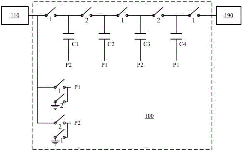
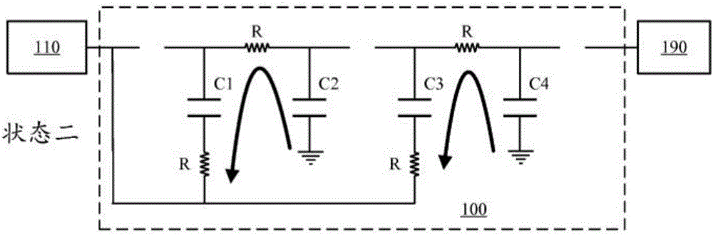
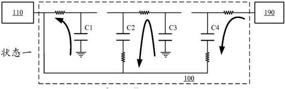
[0034] As described above, as an example, the figure 1 The charge pump 100 shown in may operate in an "adiabatic" mode, where one or both of the low voltage peripheral 110 and the high voltage peripheral 190 may include a current source. For example, patent publication WO 2012 / 151466, published on November 8, 2012 and incorporated herein by reference, describes configurations that include conditioning circuits in the source and / or load. In particular, in figure 1 and Figure 2A -B, the low voltage load 110 may effectively comprise a current source rather than a voltage source in the example of "adiabatic" operation known as a charge pump. If the current source maintains a constant current from the charge pump, then the Figure 2A The current shown in maintains an approximately constant value during the state shown. The resistive losses in the switch through which the current flows are therefore lower than in the case of a voltage load and are also substantially independent...
PUM
 Abstract
Description
Claims
Application Information
 - R&D
- Intellectual Property
- Life Sciences
- Materials
- Tech Scout
- Unparalleled Data Quality
- Higher Quality Content
- 60% Fewer Hallucinations
Browse by: Latest US Patents, China's latest patents, Technical Efficacy Thesaurus, Application Domain, Technology Topic, Popular Technical Reports.
© 2025 PatSnap. All rights reserved.Legal|Privacy policy|Modern Slavery Act Transparency Statement|Sitemap|About US| Contact US: help@patsnap.com