AC conversion circuit
A technology for converting circuits and AC voltage, applied in the direction of converting AC power input into AC power output, AC power input into DC power output, electrical components, etc., can solve the problems of increased cost and low durability, and achieve high-efficiency electric power Transformation effect
- Summary
- Abstract
- Description
- Claims
- Application Information
AI Technical Summary
Problems solved by technology
Method used
Image

Examples
Embodiment approach 1
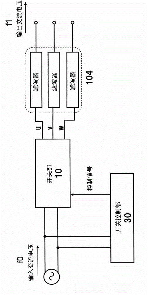
[0081] First, the AC conversion circuit of the first embodiment will be described. Figure 1E is a block diagram showing a schematic configuration of the AC conversion circuit of the present embodiment. The AC conversion circuit of the present embodiment is configured to convert a single-phase input AC voltage of frequency f0 into a relatively low three-phase output AC voltage of frequency f1. The AC conversion circuit includes: a switch unit 101 that outputs an input AC voltage to each phase through a plurality of switching elements; a zero-cross timing detection unit 102 that detects the timing (zero-cross timing) when the value of the input AC voltage becomes 0; and controls each switch The switching control unit 103 for the operation of the element; and the filter 104 for removing the high-frequency component of the output voltage of the switching unit 101 . A load is connected after the filter 104, and an AC voltage of frequency f1 is supplied to the load. The frequency...
Embodiment approach 2
[0156] Next, the AC conversion circuit of the second embodiment will be described.
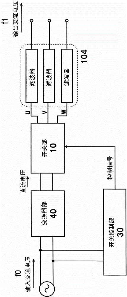
[0157] Figure 11 is a block diagram showing a schematic configuration of an AC conversion circuit in this embodiment. The AC conversion circuit of this embodiment differs from the AC conversion circuit of Embodiment 1 in that a converter unit 601 performing a rectification function is provided before the switch unit 602 to temporarily convert an input AC voltage into a DC voltage. Hereinafter, description will focus on differences from Embodiment 1, and descriptions of overlapping items will be omitted.
[0158]The AC conversion circuit of this embodiment includes: a converter unit 601 that converts an AC voltage into a DC voltage; a switch unit 602 that converts an input DC voltage to output to each phase; Timing zero-cross timing detection unit 102 ; switching control unit 603 for controlling the operation of each switching element; and filter 104 for removing high-frequency components of...
Embodiment approach 3
[0167] Next, the AC conversion circuit of the third embodiment will be described. This embodiment differs from the first and second embodiments described above in the configuration and operation of the switch control unit, but is the same in other constituent elements. Here, the second embodiment is taken as the basic configuration, and the operation of different parts will be mainly described, and the description of overlapping matters will be omitted.
[0168] Figure 17 It is a figure which shows the schematic structure of the switch control part of the AC conversion circuit in this embodiment. The switch control unit in this embodiment further includes a minimum on-time setting unit 1001 , a minimum off-time setting unit 1002 , a maximum on-time setting unit 1003 , and a maximum off-time setting unit 1004 .
[0169] The minimum on-time setting unit 1001 sends the minimum time during which each switching element is continuously in the on state to the switching signal outp...
PUM
 Abstract
Description
Claims
Application Information
 - R&D
- Intellectual Property
- Life Sciences
- Materials
- Tech Scout
- Unparalleled Data Quality
- Higher Quality Content
- 60% Fewer Hallucinations
Browse by: Latest US Patents, China's latest patents, Technical Efficacy Thesaurus, Application Domain, Technology Topic, Popular Technical Reports.
© 2025 PatSnap. All rights reserved.Legal|Privacy policy|Modern Slavery Act Transparency Statement|Sitemap|About US| Contact US: help@patsnap.com