
Novel skip adjusting device

A technology for adjusting devices and material carts, which is applied to stone processing tools, work accessories, manufacturing tools, etc., can solve problems affecting processing accuracy, poor fixing accuracy, and unfavorable production safety, so as to extend the service life, expand compatibility, and support reliable effect

Active Publication Date: 2016-08-24
苏子泷
View PDF7 Cites 0 Cited by
  • Summary
  • Abstract
  • Description
  • Claims
  • Application Information

AI Technical Summary

Problems solved by technology

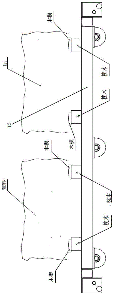
[0002] In the initial stage of stone processing, large-scale cutting machines are needed to cut stone blocks. Due to the large size of blocks, large-scale cutting machines usually carry blocks on track trucks and cut them at the cutting saw. The fixing and height adjustment of the wedge when cutting the block, because the wood is soft, makes the fixing accuracy of this method poor, and it is easy to shake during cutting to affect the cutting process, and because the block is very heavy, it is difficult to adjust the height of the block through the wooden wedge. Difficulty. In addition, this fixing method lacks a limiting structure for the horizontal position of the block, and only uses the weight and friction of the block to limit the horizontal displacement of the block.
[0003] At present, there are more and more types of stone materials for stone processing, and some light weight stones have also attracted people's attention. If the cut blocks are stones with light weight but high hardness and strength, if the blocks are only fixed with sleepers at the bottom, Then the cutting force on the block can easily push the block to move in the horizontal direction, which seriously affects the processing accuracy and is not conducive to production safety.

Method used


Image

  • Novel skip adjusting device
  • Novel skip adjusting device
  • Novel skip adjusting device

Examples


Embodiment

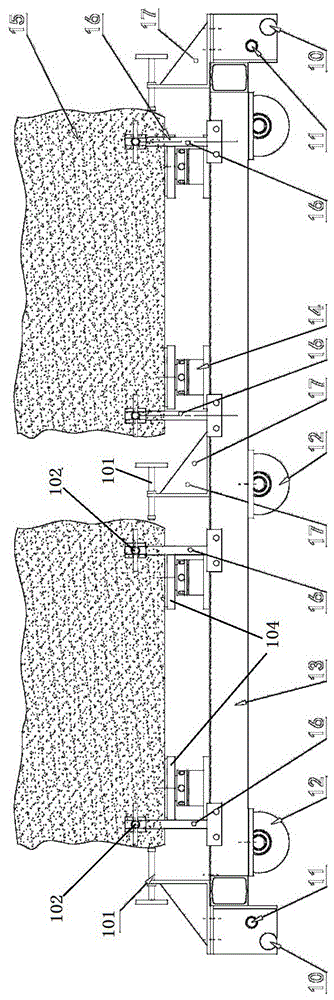
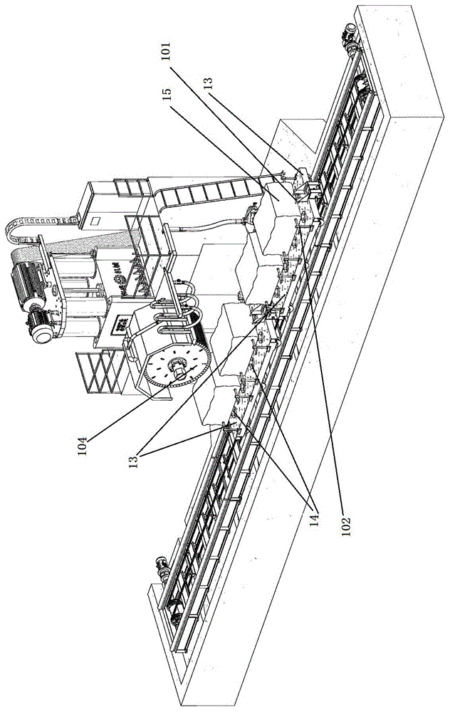
[0031] On the large-scale stone cutting machine, the feed truck 13 fixes the hook with the hook positioning pin 11 and the hook positioning pin 10 of the headstock, and the hook drives the feed truck 13 to run in a straight line on the track with the material wheel 12, and the operator hoistes the block 15 onto the feed truck On the adjustment base of the adjustment device, adjust the height of the block by adjusting the height of the support plate 104, and adjust the extension length of the push rod 101 and the push rod 102 on the side of the car to press against the block 15. Adjust the side posture of the block 15 and clamp the block 15 by adjusting the push rod 101 and the push rod 102 on the side of the car. After the block is fixed, the material cart 13 carries the block and advances to the cutting tool 103. The block material 15 is cut while the feed truck is advancing.


PUM


Abstract

The invention provides a novel skip adjusting device which is arranged on a raw material carrying face. The adjusting device comprises adjusting bases arranged in groups and side posture adjusting mechanisms arranged in groups. The adjusting bases are fixed to the raw material carrying face. A supporting plate with the adjustable height is arranged on the top of each adjusting base. Each side posture adjusting mechanism group corresponds to one adjusting base group. Each side posture adjusting mechanism comprises a side ejector rod with the adjustable jacking length, and a side ejector rod support used for fixing the side ejector rod. The side ejector rod of each side posture adjusting mechanism surrounds the peripheral edge of the corresponding adjusting base group. The side ejector rods point to raw materials on the adjusting bases. When the raw materials are loaded on a skip, the raw materials in each square are fixed by one adjusting device, the supporting plate is supported at the bottoms of the raw materials to adjust the vertical positions of the raw materials, and the side ejector rods of the side posture adjusting mechanisms jack the side walls of the raw materials to fix the raw materials. The novel skip adjusting device can fix the raw materials in the vertical and horizontal directions during the raw material cutting operation, and the raw materials can not be shaken easily in the cutting process.

Description

technical field [0001] The invention relates to a stone material processing machine, in particular to a novel material trolley adjustment device. Background technique [0002] In the initial stage of stone processing, large-scale cutting machines are needed to cut stone blocks. Due to the large size of blocks, large-scale cutting machines usually carry blocks on track trucks and cut them at the cutting saw. The fixing and height adjustment of the wedge when cutting the block, because the wood is soft, makes the fixing accuracy of this method poor, and it is easy to shake during cutting to affect the cutting process, and because the block is very heavy, it is difficult to adjust the height of the block through the wooden wedge. Difficulties. In addition, this fixing method lacks a limiting structure for the horizontal position of the block, and only uses the weight of the block and friction to limit the horizontal displacement of the block. [0003] At present, there are mor...

Claims


Application Information

Patent Timeline
IPC IPC(8): B28D7/04B28D1/24B28D7/00
CPCB28D1/24B28D7/00B28D7/04
Inventor 苏友谊
Owner 苏子泷
Learn More