A drain valve inner core tube clamping device

A technology of inner core pipe and drain valve, applied in water supply devices, flushing equipment with water tanks, buildings, etc., can solve the problems of wasting water resources and inability to achieve accurate drainage

Active Publication Date: 2018-03-16
LAB XIAMEN SANITARY FITTINGS
View PDF5 Cites 0 Cited by
  • Summary
  • Abstract
  • Description
  • Claims
  • Application Information

AI Technical Summary

Problems solved by technology

[0005] The half row of buttons and the full row of buttons of the drain valve directly drive the inner core tube to move in different strokes through the drive rod. Therefore, when users who are accustomed to long pressing the half row of buttons or the full row of buttons, the inner core tube is always lifted. state, the water sealing piece at the lower end of the inner core tube is separated from the drain outlet at the lower end of the body and is always in a draining state, which wastes water resources and cannot achieve accurate drainage

Method used


Image

  • A drain valve inner core tube clamping device
  • A drain valve inner core tube clamping device
  • A drain valve inner core tube clamping device

Examples


Embodiment Construction

[0079] The present invention will be described in detail below in conjunction with the accompanying drawings and specific embodiments. The pivot joint referred to herein means that one component can swing relative to another component.

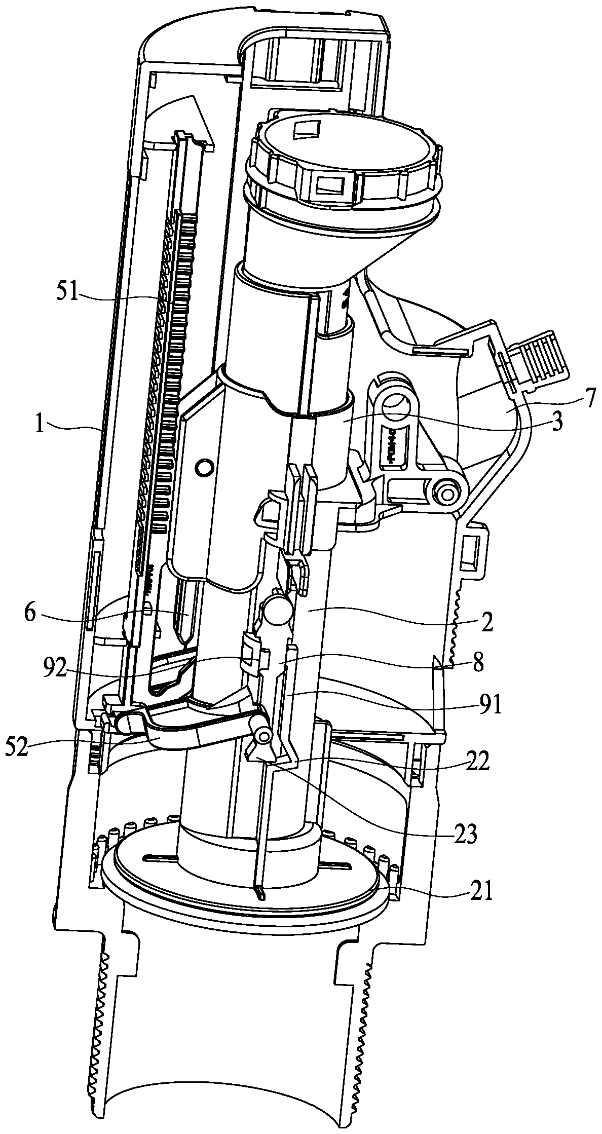
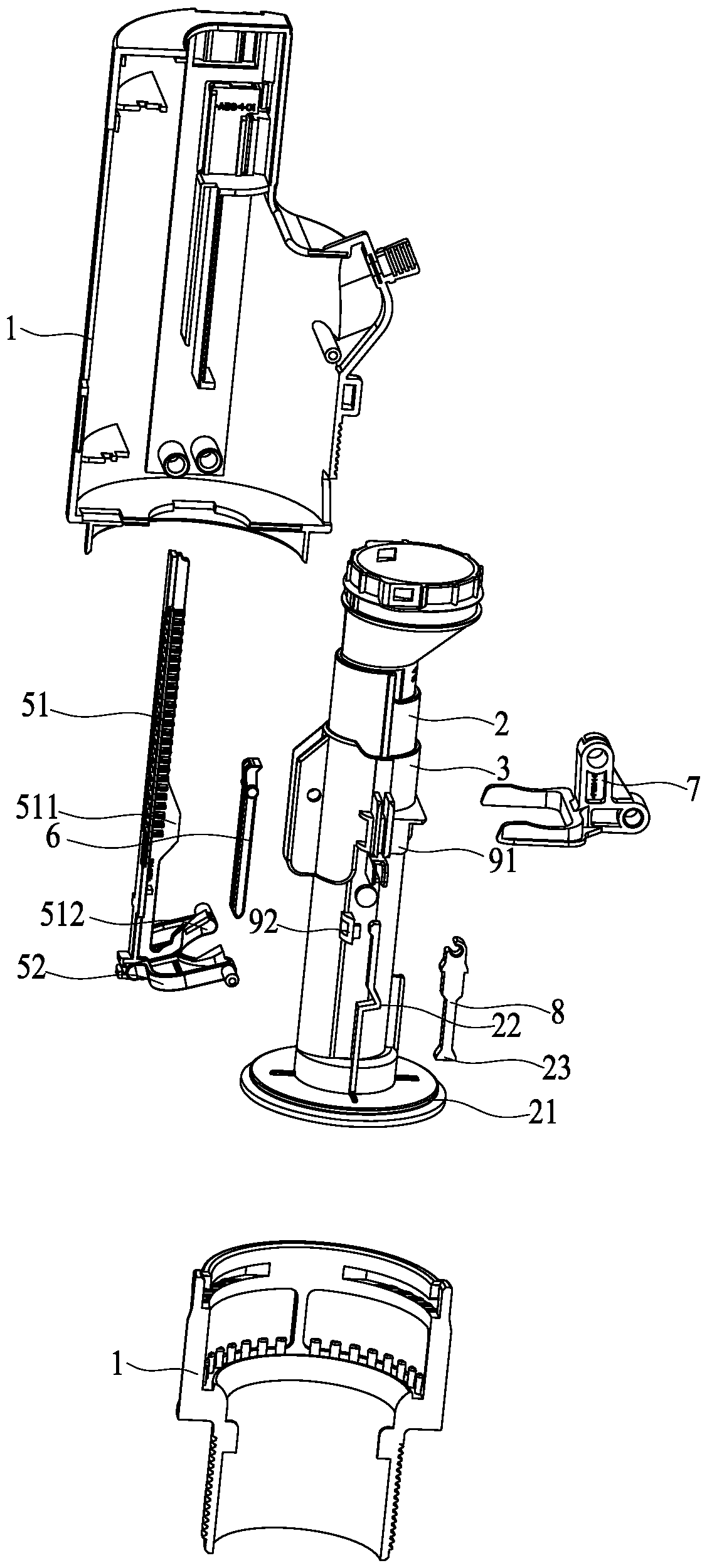
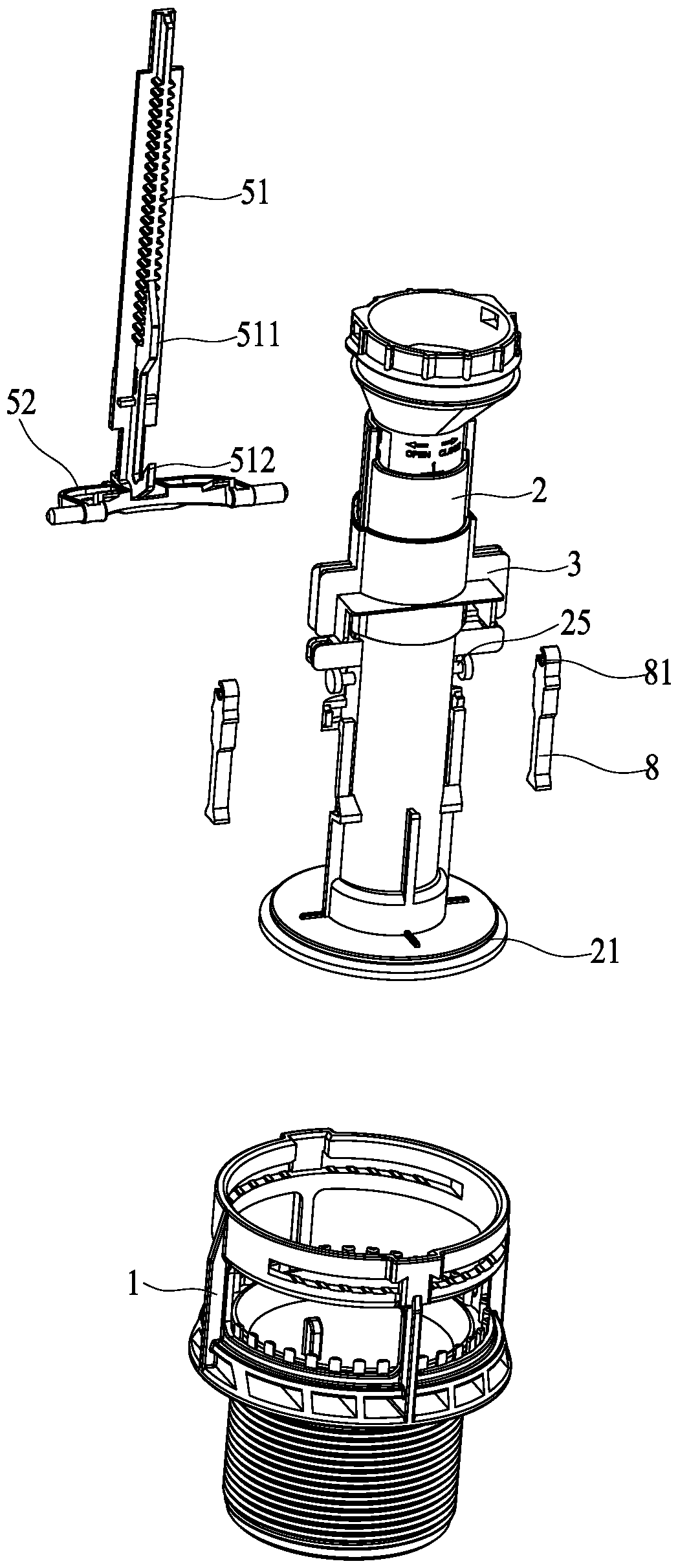
[0080] refer to Figure 1 to Figure 29 As shown, a drainage valve inner core tube clamping device disclosed by the present invention includes a main body 1, an inner core tube 2, an upper lifter 3, a half row of floating buckets 41, a full row of floating buckets 42, a half row of adjusting rods 51, Half row of brackets 52 and locking bar mechanism.

[0081] Such as Figure 1 to Figure 13 As shown, the lifter 3 is slidably connected to the upper part of the inner core tube 2, and the lifter 3 is driven up by the button mechanism 7. In this embodiment, the lifting part 3 is a sleeve, which is movably sleeved on the upper part of the inner core tube 2 , and the sleeve is driven by the button mechanism 7 to rise in the body 1 . Certainly, the...


PUM


Abstract

The invention discloses a drain valve core tube clamping device. In the water level rising state, a complete-drainage floating buoy deflects to a core tube, a complete-drainage retainer is close to the core tube, meanwhile, a half-drainage floating buoy lifts a half-drainage adjusting lever to rise, the half-drainage adjusting lever drives a half-drainage support to swing close to the core tube, a half-drainage retainer is close to the core tube, and a push and ejection portion of the half-drainage adjusting lever applies acting force to a lock bar mechanism to realize interlocking; in the water level lowering state, the complete-drainage floating buoy deviates from a core tube, the complete-drainage retainer deviates from the core tube, meanwhile, the half-drainage floating buoy lowers to drive the half-drainage adjusting lever to descend, the half-drainage adjusting lever drives the half-drainage support to swing away from the core tube, the half-drainage retainer deviates from the core tube, a squeezing portion of the half-drainage adjusting lever applies acting force to the lock bar mechanism to realize unlocking. When a drainage button is pressed for a long time, precise drainage can be realized, and water resources are saved.

Description

technical field [0001] The invention relates to the technical field of drainage valves, in particular to a locking device for an inner core tube of a drainage valve. Background technique [0002] In the prior art, there is a drain valve that roughly includes a body, a half row of buttons, a full row of buttons, a drive rod, a half row of floating buckets, a full row of floating buckets, a half row of fulcrums, a full row of fulcrums, an inner core tube and a water sealing sheet; Among them, the half row of floating barrels, the full row of floating barrels and the inner core tube are assembled in the body; one end of the driving rod is connected to the upper end of the inner core tube, and the other end of the driving rod is connected to the half row of buttons and the full row of buttons. The row of buttons is push-button or wire-controlled. Pressing the half-row or full row of buttons will make the drive rod drive the inner core tube to move in different strokes. The half...

Claims


Application Information

Patent Timeline
Patent Type & Authority Patents(China)
IPC IPC(8): E03D1/35
CPCE03D1/35
Inventor 刘永茂张子鹏
Owner LAB XIAMEN SANITARY FITTINGS
Why Eureka
Try Eureka