
Interception and drainage structure and method for deep and large crack part of rock slope body earth surface

A technology of slope body, interception and drainage, applied in drainage structures, chemical instruments and methods, water supply devices, etc., can solve the problem of increased prevention and control costs of facilities, the inability to define the installation location and form of slope surface interception and drainage measures, and the inability to accurately prevent and control landslides, etc. problem, to achieve the effect of increasing stability and reducing transient high pressure void water

Inactive Publication Date: 2021-06-04
INST OF GEOMECHANICS
View PDF6 Cites 0 Cited by
  • Summary
  • Abstract
  • Description
  • Claims
  • Application Information

AI Technical Summary

Problems solved by technology

In the existing technology, the common landslide drainage measures include slope surface cut-off drainage ditches, drainage tunnels, drainage blind ditches, etc. However, the slope surface cut-off drainage measures cannot clearly define the location and form of construction, and it is difficult to prevent surface runoff or heavy rainfall at the top of cracks Into deep and large fissures, it is impossible to accurately prevent and control such landslides, and blindly increasing facilities will increase unnecessary prevention and control costs

Method used


Image

  • Interception and drainage structure and method for deep and large crack part of rock slope body earth surface
  • Interception and drainage structure and method for deep and large crack part of rock slope body earth surface

Examples


Embodiment Construction

[0022] The technical problems, technical solutions and advantages of the present invention will be explained in detail below by referring to exemplary embodiments. The exemplary embodiments described below are only for explaining the present invention, but not construed as limiting the present invention.

[0023] Those skilled in the art can understand that, unless otherwise defined, all terms (including technical and scientific terms) used herein have the same meaning as commonly understood by one of ordinary skill in the art to which this invention belongs. It should also be understood that terms such as those defined in commonly used dictionaries should be understood to have meanings consistent with their meaning in the context of the prior art and will not be used in an idealized or overly formal sense unless defined herein to explain.

[0024] Due to tectonic activities, rocky slopes will develop joints and fissures. Under the action of heavy rainfall, rainwater will dir...


PUM


Abstract

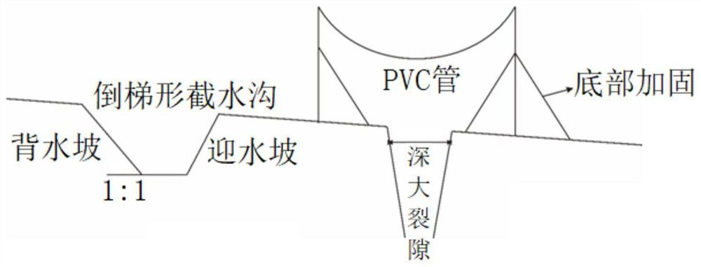
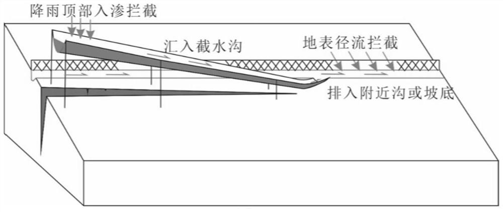
The invention provides an interception and drainage structure and method for a deep and large crack part of a rock slope body earth surface. The problems that in the prior art, slope body earth surface interception and drainage measures are not high in pertinence and inaccurate in interception and drainage are solved. The interception and drainage structure comprises an intercepting ditch and an overhead water guide device, the intercepting ditch is arranged on the rear edge of a deep and large crack and is parallel to the crack trend, the two ends of the intercepting ditch form a preset fall, and the low-water-level end of the intercepting ditch communicates with a surrounding low-water-level natural ditch; the overhead water guide device is arranged in the moving direction of the crack, one end of the overhead water guide device is suspended at the top of the crack, the other end of the overhead water guide device communicates with the intercepting ditch, and a preset included angle is formed between the water guide device and the ground; and rainwater at the top of the crack is guided into the intercepting ditch through overhead water guide equipment, and surface runoff is guided into the intercepting ditch and then discharged into the natural ditch. According to the interception and drainage structure and method for the deep and large crack part of the rock slope body earth surface, targeted and accurate water interception and drainage are achieved, a high-pressure water head is prevented from being formed in the deep and large crack, transient high-pressure gap water in a slope body is reduced, and the stability of the slope body is improved.

Description

technical field [0001] The invention belongs to the field of geological disaster prevention, and in particular relates to a structure and method for intercepting and draining deep and large fissures on the surface of a rocky slope body. Background technique [0002] In rocky slope areas, under severe weather conditions such as rainfall, landslides and other disasters may occur. For rocky slopes, due to the influence of internal dynamic geological effects such as tectonic activities, one or several groups of joint fissures are distributed on rocky slopes. In the actual geological survey, it was found that many slopes developed with strike and aspect For vertical or near-vertical joint fissures, the unstable slope body will undergo creep deformation, which will lead to the continuous extension of this group of joints, thus forming a tension "v" extending from several meters to tens of meters on the landslide body and trailing edge deep fissures. The permeability of rock mass...

Claims


Application Information

Patent Timeline
Patent Type & Authority Applications(China)
IPC IPC(8): E03F3/04E03F3/02E03F5/14
CPCE03F3/02E03F3/04E03F3/046E03F5/14
Inventor 赵志男李滨高杨
Owner INST OF GEOMECHANICS
Learn More