Gas valve with improved sealing characteristics

A technology for air valves and seals, applied in the field of air valves, can solve problems such as the inability to calibrate the size deviation of elastomer seals, and achieve the effect of improving the manufacturing process

Active Publication Date: 2016-08-24
ROBERT BOSCH GMBH
View PDF6 Cites 0 Cited by
  • Summary
  • Abstract
  • Description
  • Claims
  • Application Information

AI Technical Summary

Problems solved by technology

However, production-related dimensional deviations of the elastomer seal cannot be corrected

Method used


Image

  • Gas valve with improved sealing characteristics
  • Gas valve with improved sealing characteristics
  • Gas valve with improved sealing characteristics

Examples


Embodiment Construction

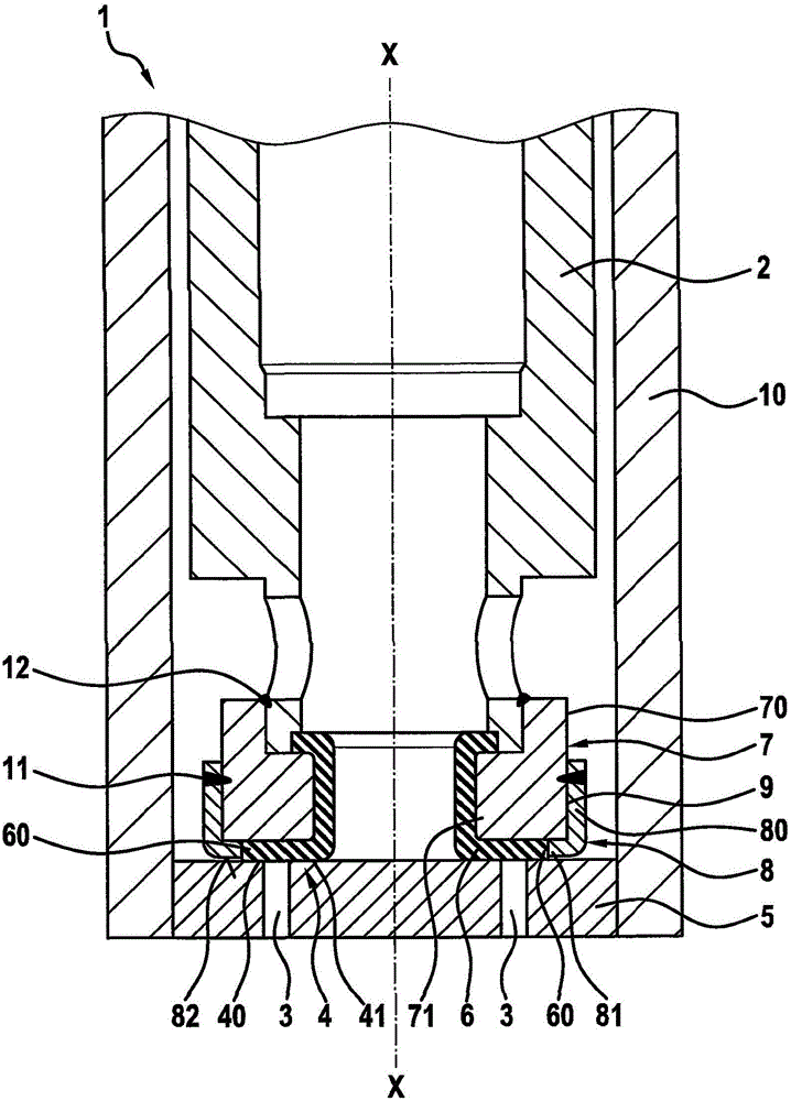
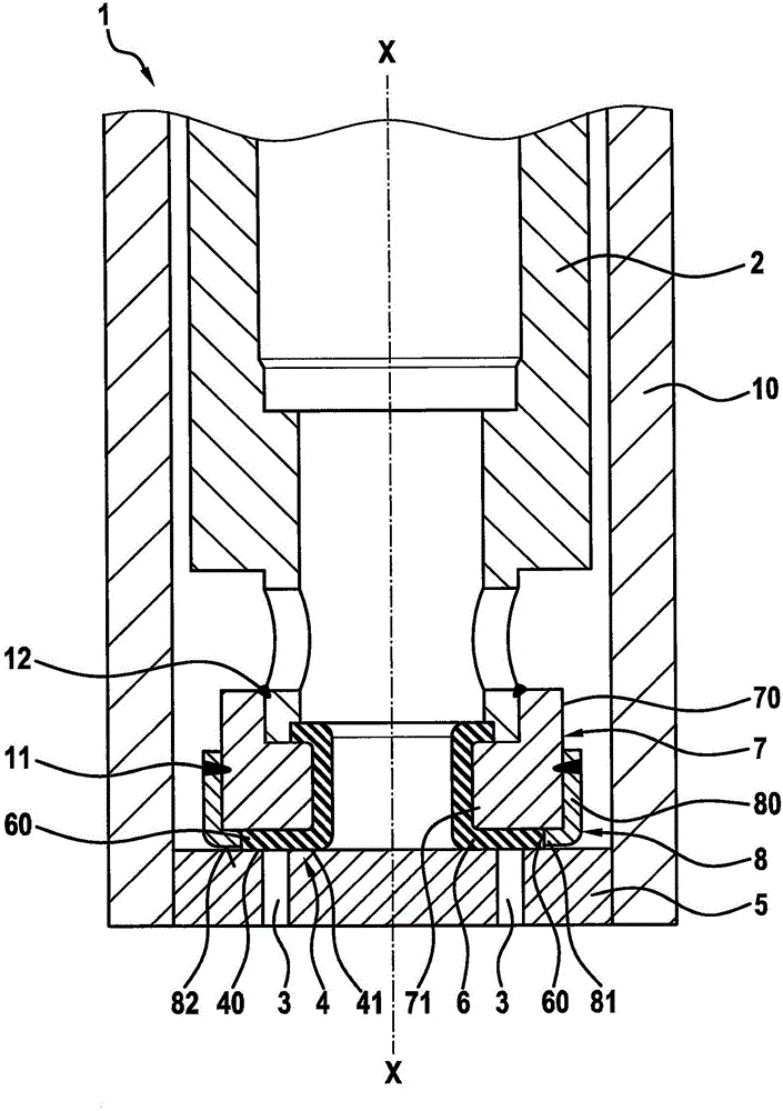
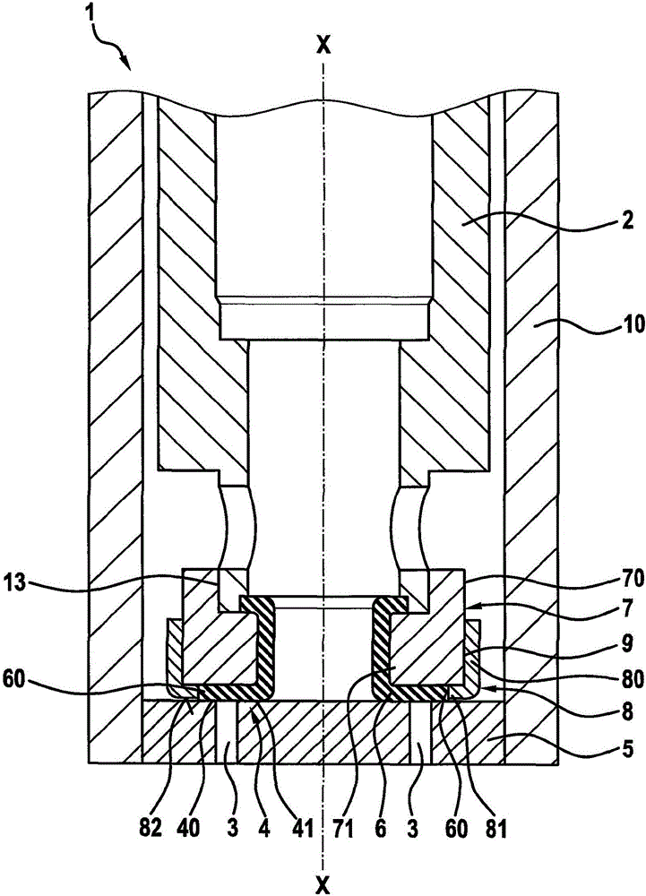
[0021] Refer to the following figure 1 The valve 1 according to the first embodiment of the present invention will be described in detail.

[0022] as by figure 1 It can be clearly seen that the valve 1 comprises a movable valve closing element 2 , which in this embodiment is a magnetic armature. The valve closing element 2 is designed as a hollow cylinder, so that gaseous fuel can be guided not only inside the valve closing element 2 but also outside.

[0023] The valve closing element 2 is arranged in a valve body 10 which is closed by a sealing gasket 5 providing a valve seat. The valve body 10 is a hollow cylindrical component and seals the sealing gasket 5 at its free end. A plurality of kidney-shaped through-openings 3 are provided in the sealing washer 5 , which are released and closed by means of the valve closing element 2 . figure 1 Shows the closed state of the valve.

[0024] In order to achieve reliable sealing of gaseous media, an elastomer seal 6 is provide...


PUM


Abstract

The invention relates to a gas valve for controlling a gaseous medium, comprising a movable valve closure element (2) for releasing and closing at least one passage opening (3), a sealing seat (4) between a fixed valve component (5) and the valve closing element (2), an elastomer sealing element arranged on a sealing element carrier (7), the sealing element carrier (7) connected to the valve closing element (2), and a separate adjusting element (8). The separate adjusting element (8) is arranged on the seal carrier (7) and provided as a stop in the closed state of the valve and, in the open state of the valve, defines an abutment of the elastomer seal (6) projecting in the axial direction (XX) via a stop surface (82) of the adjusting element (8).

Description

technical field [0001] The invention relates to a gas valve with an adjusting element and an elastomer seal in order to provide an improved tightness of the gas valve in the closed state. Background technique [0002] Gas valves are known from the prior art in various designs. In the motor vehicle sector, gaseous fuels, such as natural gas or hydrogen, have recently been increasingly used in addition to liquid fuels. Frequently, injection molding valves known here for liquid fuels are simply and unchanged for gaseous media. However, valves for liquid media often do not meet the specific requirements of gaseous media. For sealing off gaseous media, especially elastomeric seals are particularly suitable. Such elastomeric seals are usually produced by means of an injection molding process. In this case, however, relatively large tolerances (in particular in the opening and closing direction of the valve) arise as a result of production. However, this leads to undesirably l...

Claims


Application Information

Patent Timeline
Patent Type & Authority Applications(China)
IPC IPC(8): F02M21/02
CPCF02M21/023F02M21/0266F16K1/36F16K1/46F16K25/00Y02T10/30
Inventor J·拜尔R·林德纳
Owner ROBERT BOSCH GMBH
Why Eureka
Try Eureka