Aluminum profile connection structure and corner code for connection structure

A technology for connecting structures and aluminum profiles, applied in the direction of connecting components, rods, mechanical equipment, etc., can solve problems such as less degrees of freedom, loose screw connections, breakage, etc., and achieve fast and convenient installation, reasonable and stable positioning, and fast positioning connections Effect

Active Publication Date: 2018-03-30
FUJIAN MINLU LIGHTWEIGHT AUTOMOBILE MFG CO LTD
View PDF7 Cites 1 Cited by
  • Summary
  • Abstract
  • Description
  • Claims
  • Application Information

AI Technical Summary

Problems solved by technology

[0002] The L-shaped corner code is used to connect two aluminum profiles that are perpendicular to each other. At present, the commonly used connection method between the L-shaped corner code and the aluminum profile is mainly: the two perpendicular sides of the L-shaped corner code are the outer sides. Fit the two aluminum profiles perpendicular to each other of the peripheral, and then use screws to fix the corner code and the aluminum profile. , making it difficult to adjust the positioning relationship between the corner code and the aluminum profile. In addition, most of the shear force between the corner code and the aluminum profile acts on the screws. The stability and life of the connection between aluminum profiles

Method used


Image

  • Aluminum profile connection structure and corner code for connection structure
  • Aluminum profile connection structure and corner code for connection structure
  • Aluminum profile connection structure and corner code for connection structure

Examples


Embodiment 1

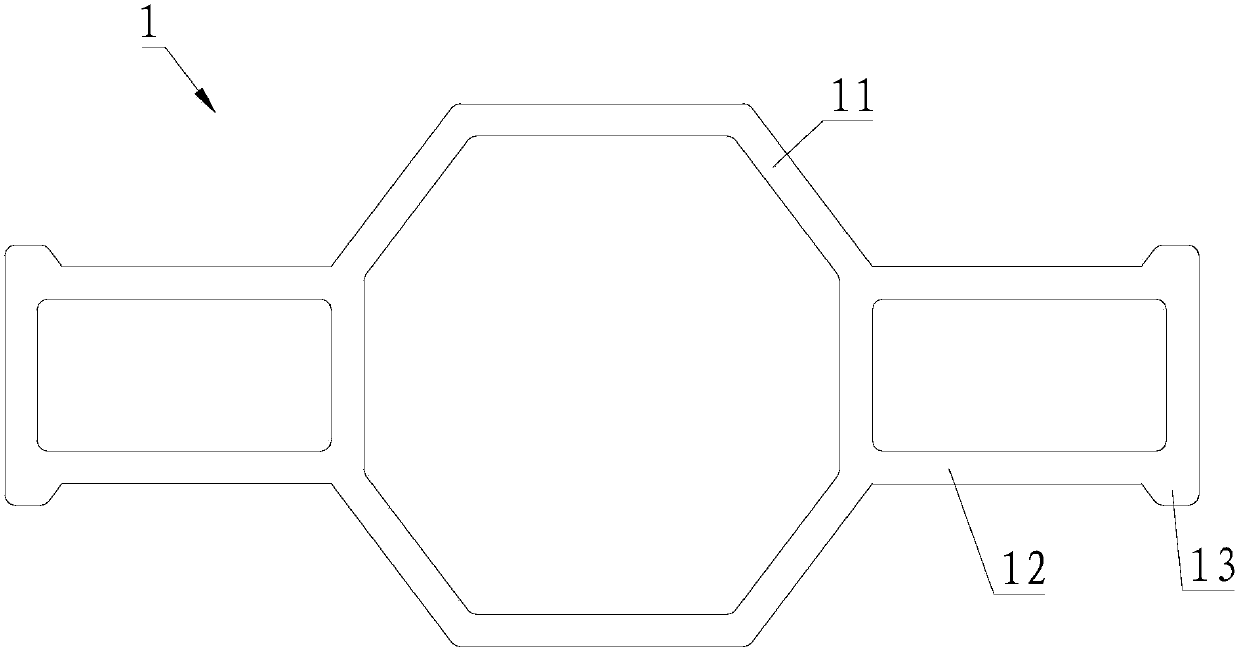
[0028] Please refer to Figure 1 to Figure 6 , Embodiment 1 of the present invention is:

[0029] A connection structure between an aluminum profile 1 and a corner bracket, comprising two aluminum profiles 1 and corner brackets arranged perpendicularly to each other, the corner bracket includes a pair of symmetrically arranged L-shaped corner brackets 2, and the aluminum profile 1 includes an aluminum profile The main body 11, the outer surface of the aluminum profile main body 11 is provided with a door-shaped protrusion 12, and the inner surface of the angle code piece 2 is provided with a first groove 21 with an L-shaped cross section. The angle code piece 2 The first groove 21 of the first groove 21 is connected with the gate-shaped protrusions 12 of the two mutually perpendicular aluminum profiles 1 at the same time, and the two corner code pieces 2 are clamped and arranged opposite to each other; the corners of the gate-shaped protrusions 12 A trapezoidal protrusion 13 ...

Embodiment 2

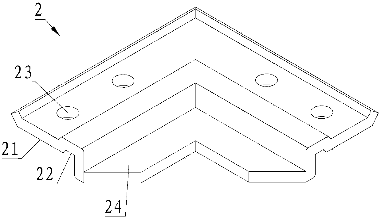
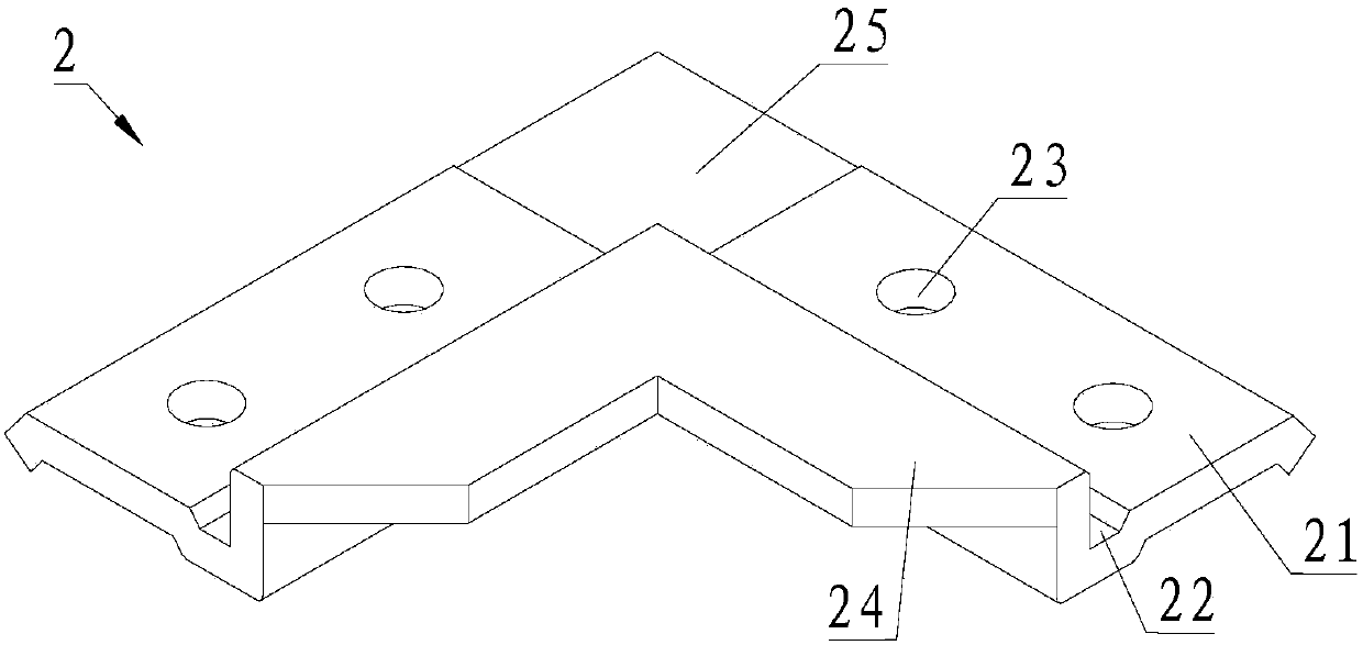
[0040] Please refer to Figure 2 to Figure 6 , the second embodiment of the present invention is:

[0041] An angle code for a connection structure, including a pair of symmetrically arranged L-shaped angle code pieces 2, a first groove 21 with an L-shaped cross-section is provided on the inner side of the angle code piece 2, and the angle code piece 2 Through the first groove 21 and the two external aluminum profiles 1 that are perpendicular to each other are attached and connected, a pair of corner codes 2 are clamped to each other, and a pair of first grooves 21 of the corner code 2 The second through hole 23 is provided on the opposite surface, and the second through hole 23 is adapted to the external screw 3, and the second through hole 23 is provided on the opposite surface of the first groove 21 of the two angle code pieces 2. Groove 22, the cross-sectional shape of the second groove 22 is trapezoidal, the second groove 22 is connected with the peripheral aluminum profil...


PUM


Abstract

The invention provides an aluminum profile connecting structure and an angle code for the connecting structure. The aluminum profile connecting structure comprises two aluminum profiles which are mutually vertically arranged, and the angle code, wherein the angle code comprises a pair of symmetrically-arranged L-shaped angle code sheets; each aluminum profile comprises an aluminum profile body of which the outer side surface is provided with an inverted U-shaped bump; a first groove of which the section is L-shaped is formed in the inner side surface of each angle code sheet, and the first grooves of the angle code sheets are synchronously clung to the inverted U-shaped bumps of the two aluminum profiles which are mutually vertically arranged. According to the aluminum profile connecting structure, a pair of symmetrically-arranged angle code sheets is utilized to realize the positioning connection of the two aluminum profiles which are mutually vertically arranged, so that the mounting and positioning are quick and convenient.

Description

technical field [0001] The invention relates to the technical field of aluminum profiles, in particular to an aluminum profile connection structure and a corner code for the connection structure. Background technique [0002] The L-shaped corner code is used to connect two aluminum profiles that are perpendicular to each other. At present, the commonly used connection method between the L-shaped corner code and the aluminum profile is mainly: the two perpendicular sides of the L-shaped corner code are the outer sides. The two aluminum profiles perpendicular to each other are attached to the peripheral, and then the corner code and the aluminum profile are fixedly connected with screws. This method is determined as: the corner code and the aluminum profile are positioned through the surface, and the degree of freedom is limited. , making it difficult to adjust the positioning relationship between the corner code and the aluminum profile. In addition, most of the shear force b...

Claims


Application Information

Patent Timeline
Patent Type & Authority Patents(China)
IPC IPC(8): F16B7/18
CPCF16B7/187
Inventor 肖开政张东贵范永达周强
Owner FUJIAN MINLU LIGHTWEIGHT AUTOMOBILE MFG CO LTD
Why Eureka
Try Eureka