
T-O-F depth imaging device rendering depth image of object and method thereof

一种T-O-F、成像装置的技术,应用在测量装置、图像分析、图像数据处理等方向

Active Publication Date: 2016-08-24
SAMSUNG ELECTRONICS CO LTD
View PDF5 Cites 25 Cited by
  • Summary
  • Abstract
  • Description
  • Claims
  • Application Information

AI Technical Summary

Problems solved by technology

T-O-F cameras with global demodulators only capture intensity samples sequentially

Method used


Image

  • T-O-F depth imaging device rendering depth image of object and method thereof
  • T-O-F depth imaging device rendering depth image of object and method thereof
  • T-O-F depth imaging device rendering depth image of object and method thereof

Examples


Embodiment Construction

[0044] As already mentioned, the present description is about depth imaging devices, systems and methods. Embodiments are now described in more detail.

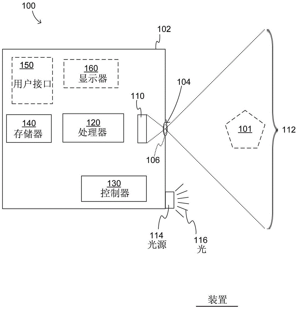
[0045] figure 1 is a block diagram of an apparatus 100, which may be implemented according to many different embodiments. For example, the apparatus 100 may be a depth imaging apparatus configured to render a depth image of the object 101 or a person. A "depth image" of an object is not an image in the conventional sense, but a way of presenting information about the distance (depth, or extent) of various parts of the object from the camera. For another example, device 100 may be a conventional imaging device, such as a camera. In some embodiments, the device 100 is both a depth imaging device and a conventional imaging device, since devices of this type have commonalities that can be used synergistically.

[0046] The device 100 may have a housing 102, which may also be referred to as a housing. Opening 104 is provided ...


PUM


Abstract

A T-O-F depth imaging device rendering a depth image of an object and a method thereof are provided. In embodiments, a T-O-F depth imaging device renders a depth image of an object that has corrected depth values. The device includes a pixel array that uses an Electronic Rolling Shutter scheme. The device also includes a light source that transmits towards the object light that is modulated at an operating frequency, and an optical shutter that opens and closes at the operating frequency. The optical shutter further modulates the light that is reflected from the object, before it reaches the pixel array. The transmission of the light and the operation of the shutter change phase relative to each other while at least one of the pixels is sensing the light it receives, which permits a faster frame rate. Depth is determined by the amount of light sensed by the pixels, and a correction is computed to compensate for the changing phase.

Description

[0001] This patent application claims priority to US Provisional Patent Application Serial No. 62 / 100,464, filed January 6, 2015, and US Provisional Patent Application No. 14 / 883,598, filed October 14, 2015, in the United States Patent and Trademark Office, The disclosure of said US Provisional Patent Application is incorporated herein by reference. technical field [0002] The present description relates to depth imaging devices, systems, and methods. Background technique [0003] Ranging devices are used for range sensing, ie to measure the distance from these devices to objects or people. Range sensing is also known as ranging, distance sensing or depth sensing. Certain distance measuring devices (sometimes referred to as imaging range sensors) are capable of performing multiple distance measurements simultaneously in different directions within a particular solid angle or field of view (FOV). A set of distance values ​​measured in this manner can be converted into a 3-...

Claims


Application Information

Patent Timeline
Patent Type & Authority Applications(China)
IPC IPC(8): G06T7/00G01S7/4914G01S17/894
CPCG01S17/36G01S7/4816G01S7/4914G01S17/894
Inventor 格雷戈里·瓦力古尔斯基莉利亚·奥夫相尼科夫朴勇和
Owner SAMSUNG ELECTRONICS CO LTD
Learn More