Separated grouting device in drilled hole and sectional grouting operation process

A technology of grouting device and operation process, which is applied in earth-moving drilling, infrastructure engineering, wellbore/well components, etc. Problems such as difficulty of grouting again

Inactive Publication Date: 2016-08-31
SHANDONG UNIV
View PDF6 Cites 19 Cited by
  • Summary
  • Abstract
  • Description
  • Claims
  • Application Information

AI Technical Summary

Problems solved by technology

The progressive grouting process is controlled by grouting drilling from the shallow layer to the deep layer of the surrounding rock, and the grouting is reinforced step by step until the design depth. When the surrounding rock is weak and unevenly distributed, the injected grout faces the phenomenon of repeated grouting on the exposed shallow surrounding rock
Moreover, when the high-pressure water gushing is exposed in the deep part of the borehole, it is difficult for the grout to be completely injected into the deep injection area, resulting in repeated grouting of the weak surrounding rock in the shallow part, and it is difficult to achieve the purpose of uniform grouting reinforcement for the entire borehole
At the same time, once the rigid grouting pipe fails to be grouted, it cannot be retracted, and it will bring certain difficulties to re-grouting at the same distance in the borehole; in addition, the retreating grouting currently mainly includes TSS pipes, sleeve valve pipes, etc. Although the two processes have separate grouting effects, both of them cannot be reused because the grouting pipe cannot be lifted out after grouting; when using the WSS grouting process, it is difficult to achieve separate uniform grouting In addition, there is a danger that the grouting pipe will be sealed by the grout in the hole

Method used


Image

  • Separated grouting device in drilled hole and sectional grouting operation process
  • Separated grouting device in drilled hole and sectional grouting operation process
  • Separated grouting device in drilled hole and sectional grouting operation process

Examples


Embodiment

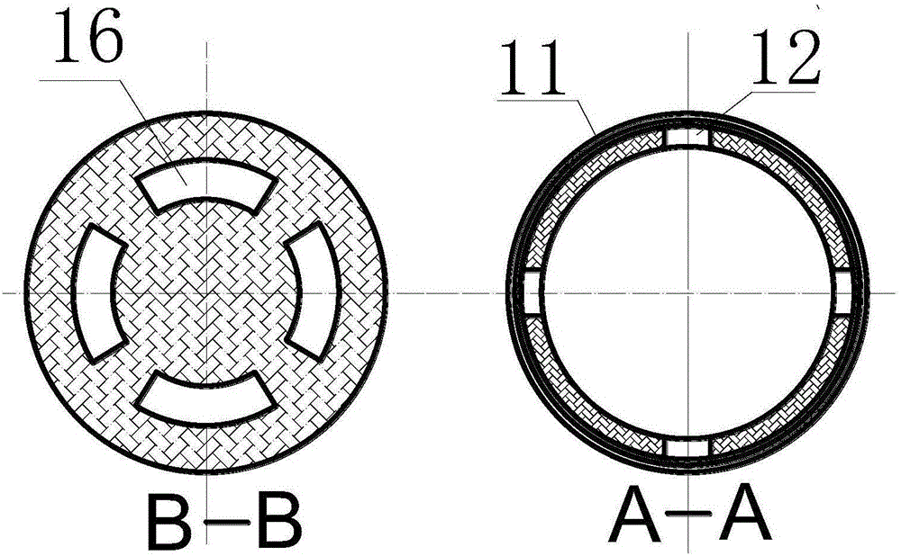
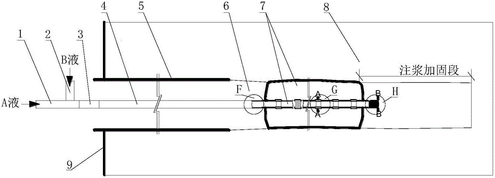
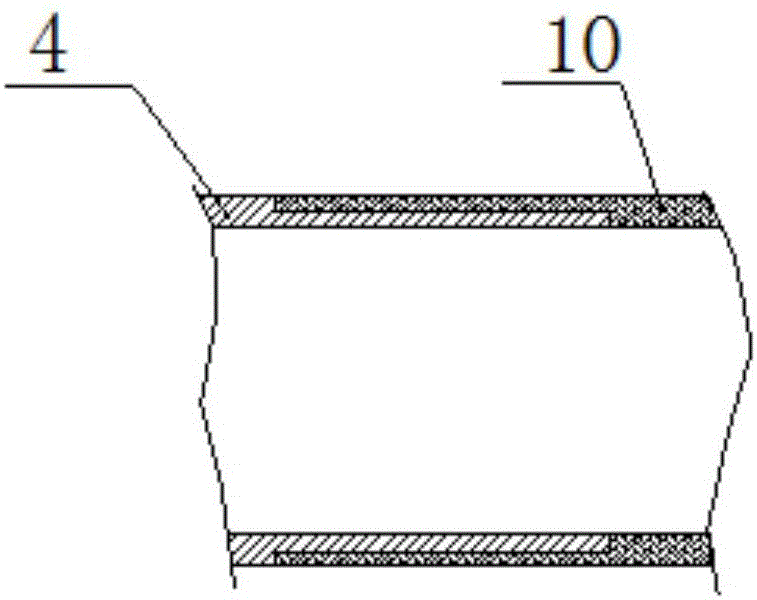
[0064] Example: A highway tunnel in Cenxi City, Guangxi encountered a fully weathered granite stratum, which was rich in high-pressure water, and the stratum softened severely after being exposed to water. Water and mud inrush disasters were encountered many times during tunnel excavation, which seriously affected the progress of the project . In order to control the geological disaster of water and mud inrush, curtain grouting construction was carried out around the tunnel. Hole collapse and large water gushing often occur in curtain grouting drilling, which indicates that the surrounding rock of the drilling hole is loose and weak, it is difficult to drill holes, and the hole wall is irregular. The cost is high and the overall efficiency is poor. Moreover, the phenomenon of repeated grouting for shallower hole sections after grouting reinforcement also appeared. After the study, the separate grouting device in the borehole and the segmented grouting operation process of th...


PUM


Abstract

The invention discloses a separated grouting device in a drilled hole and a sectional grouting operation process. The device comprises stop-grouting plug assemblies and grouting pipes. A check valve is arranged at one end of one grouting pipe which is provided with multiple stop-grouting plug overflow holes. Pressing belts for blocking the stop-grouting plug overflow holes are arranged on the stop-grouting plug overflow holes outside the corresponding grouting pipe. The pressing belts are flushed open by grout under set pressure, and an expanding non-woven bag outside the corresponding grouting pipe is filled with the grout. The grout can flush open the check valve under set pressure to carry out grouting reinforcement. A grouting lifting tube is detachably mounted at the other end of the corresponding grouting pipe. By means of the separated grouting device in the drilled hole and the sectional grouting operation process, separated grouting can be carried out in irregular loose and weak surrounding rock and even water-rich surrounding rock, the grouting lifting tube can be lifted out after grouting, separated grouting can be carried out in different positions in the same drilled hole, and through separated grouting, the problem that grout is repeatedly injected into shallow surrounding rock and cannot be easily conveyed to deep surrounding rock is solved.

Description

technical field [0001] The invention belongs to the field of grouting reinforcement for underground projects such as mines, tunnels, water conservancy and hydropower, and specifically relates to a separate grouting device in boreholes and a segmented grouting operation process. Background technique [0002] In the grouting reinforcement of underground engineering, loose and weak or even water-rich surrounding rocks are often encountered. In the grouting reinforcement of such surrounding rocks, the biggest problem faced is that the borehole collapses seriously and the porosity rate is low. When carrying out systematic grouting reinforcement to this kind of surrounding rock, there are two techniques of forward or backward grouting. The progressive grouting process is controlled by grouting drilling from the shallow layer to the deep layer of the surrounding rock, and the grouting is reinforced step by step until the design depth. When the surrounding rock is weak and unevenly...

Claims


Application Information

Patent Timeline
Patent Type & Authority Applications(China)
IPC IPC(8): E21D9/00E21B33/12E02D15/04
CPCE21D9/001E02D15/04E21B33/1208
Inventor 张庆松李术才潘光明杨磊周小生张霄刘人太李召峰王凯林荣峰随海通刘春国
Owner SHANDONG UNIV
Why Eureka
Try Eureka