Rail sensor mounting structure and application

A technology of installation structure and sensor, applied in transportation and packaging, railway signal and safety, vehicle route interaction equipment, etc. The effect of shifting and increasing workload

Active Publication Date: 2016-09-07
陕西航泰电气股份有限公司
View PDF11 Cites 3 Cited by
  • Summary
  • Abstract
  • Description
  • Claims
  • Application Information

AI Technical Summary

Problems solved by technology

[0004] The purpose of the present invention is to overcome the problems in the prior art that the left and right deviation of the track installation detection device cannot be installed and fixed, and the construction of the cement foundation bed has a large amount of engineering, high construction costs, long construction period, and inconvenience to transportation.

Method used


Image

  • Rail sensor mounting structure and application
  • Rail sensor mounting structure and application
  • Rail sensor mounting structure and application

Examples


Embodiment 1

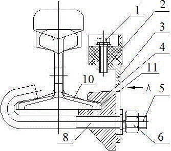
[0023] This embodiment provides a track sensor installation structure, including a gauge bar iron clip 4 fixed on the gauge bar 10 on the outside of one side of the track, a bracket 3 arranged on the outside of the gauge bar iron clip 4, and a fixed gauge The iron clamp 4 for the rod and the locking bolt 5 of the bracket 3, the first through hole 8 is provided at the lower part of the iron clamp 4 for the gauge rod, the second through hole 9 is provided at the lower part of the support 3, and the locking bolt One end of 5 is fixed on the lower edge of the track on the other side, and the other end is fixed by nut 6 after passing through the first through hole 8 and the second through hole 9;

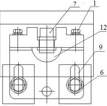
[0024] The top of the bracket 3 is provided with a fixed block 2 on which a sensor 7 is installed.

[0025] Installation process:

[0026] Dig an installation hole under the track of the required detection site, fix one end of the locking bolt 5 with the lower edge of one side of the tr...

Embodiment 2

[0029] On the basis of embodiment 1, this embodiment provides a kind of figure 1 , 2 In the track sensor installation structure shown, the locking bolt 5 is a bent bolt with one end bent, and the bent end of the bent bolt faces upwards and clamps the lower edge of the track on the other side.

[0030] Installation process:

[0031] Dig an installation pit under the track of the required detection site, fix the gauge bar on the gauge bar 10 on the outside of one side of the track with iron clamp 4, and use a bent bolt to bend one end to clamp the lower edge of the other side of the track to fix, and then the gauge The first through hole 8 of the iron clip 4 for the rod and the second through hole 9 of the bracket 3 pass through the bent bolts sequentially and then locked and fixed with the nut 6; then the fixing block 2 is fixed on the bracket 3 with the bolt 1, and the sensor 7 Fix it on the fixed block 2, lock it after reaching a suitable detection position, and finally con...

Embodiment 3

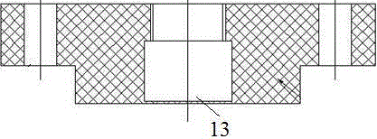
[0034] On the basis of Embodiment 2, this embodiment provides a rail sensor installation structure, such as figure 1 As shown, a U-shaped groove 11 is arranged in the middle of the iron clip 4 for the gauge rod, and a first through hole 8 is symmetrically arranged about the U-shaped groove 11, as Figure 4 As shown, the lower end of the bracket 3 is symmetrically provided with a second through hole 9 corresponding to the two first through holes 8 of the iron clip 4 for the gauge rod.

[0035] Installation process:

[0036] Dig an installation pit under the track of the required detection site, and the gauge bar is stuck on the gauge bar 10 on the outside of one side of the track with the U-shaped groove 11 of the iron clip 4, and two symmetrically placed on both sides of the gauge bar 10 One end of the bent bolt is bent and fixed to the lower edge of the track on the other side, and then the two first through holes 8 of the iron clip 4 for the gauge rod and the two second thr...


PUM


Abstract

The invention provides a rail sensor mounting structure and application. The rail sensor mounting structure comprises an iron clamp, a support and a lock bolt, wherein the iron clamp is fixed to a gauge rod on the outer side of a rail on one side and used for the gauge rod; the support is arranged on the outer side of the iron clamp for the gauge rod; and the lock bolt is used for fixing the iron clamp for the gauge rod and the support. The iron clamp for the gauge rod is provided with a first through hole. The lower end of the support is provided with a second through hole. One end of the lock bolt is fixed to the lower edge of a rail on the other side. The other end of the lock bolt penetrates through the first through hole and the second through hole and then is fixed through a nut. The top end of the support is provided with a fixing block. A sensor is mounted on the fixing block. By adopting the rail sensor mounting structure provided by the invention, the problems that traditional deep foundation pit type or cement foundation bed rails are large in construction amount, high in construction cost and long in construction cycle in the prior art are solved.

Description

technical field [0001] The invention belongs to the technical field of mine car detection, and in particular relates to a track sensor installation structure and a mine car detection device. Background technique [0002] Rail transit facilities have different requirements and standards for different applications. Due to the limitation of installation space or installation location in some places, the direction or position of components needs to be adjusted when installing these facilities. However, most of the current installation components have fixed structures After installation, there will be problems of deviation from the installation position or an angle between the installation position, left-right deviation or even installation and fixation, so that it cannot adapt to these special requirements, and problems of long-term operation safety and measurement accuracy cannot be met. [0003] The production and transportation of mines must be realized by rail mine cars, so ...

Claims


Application Information

Patent Timeline
Patent Type & Authority Applications(China)
IPC IPC(8): B61L1/02B61L1/18
CPCB61L1/02B61L1/181
Inventor 杜磊王军祥于文成
Owner 陕西航泰电气股份有限公司
Why Eureka
Try Eureka