Unlock instant, AI-driven research and patent intelligence for your innovation.

Spherical hinge constraining method capable of realizing hinge joint compression on 1000-t testing machine

A testing machine and ball hinge technology, which is applied in the direction of applying stable tension/pressure to test the strength of materials, can solve the problems of multi-axis components and compression, and achieve the effect of convenient and reliable hinge compression test

Inactive Publication Date: 2016-09-07
CHONGQING UNIV
View PDF28 Cites 10 Cited by
  • Summary
  • Abstract
  • Description
  • Claims
  • Application Information

AI Technical Summary

Problems solved by technology

[0005] The purpose of the present invention is to solve the pressure problem of long-axis members with a large number and specifications similar to those of a large tonnage. Combined with the loading conditions of the testing machine, a method of adding a pressure sensor to the spherical hinge at the top of the testing machine to limit the rotation of the spherical hinge is proposed.

Method used


Image

  • Spherical hinge constraining method capable of realizing hinge joint compression on 1000-t testing machine
  • Spherical hinge constraining method capable of realizing hinge joint compression on 1000-t testing machine
  • Spherical hinge constraining method capable of realizing hinge joint compression on 1000-t testing machine

Examples


Embodiment 1

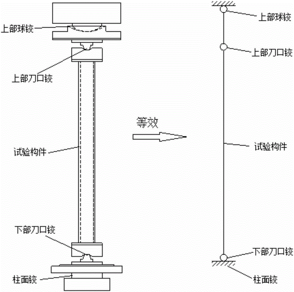
[0021] This embodiment provides a 1000t testing machine to realize the spherical hinge restraint method under pressure of the hinge, so as to facilitate the test that needs to limit the rotational restraint of the spherical hinge.

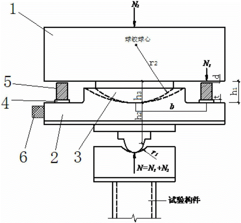
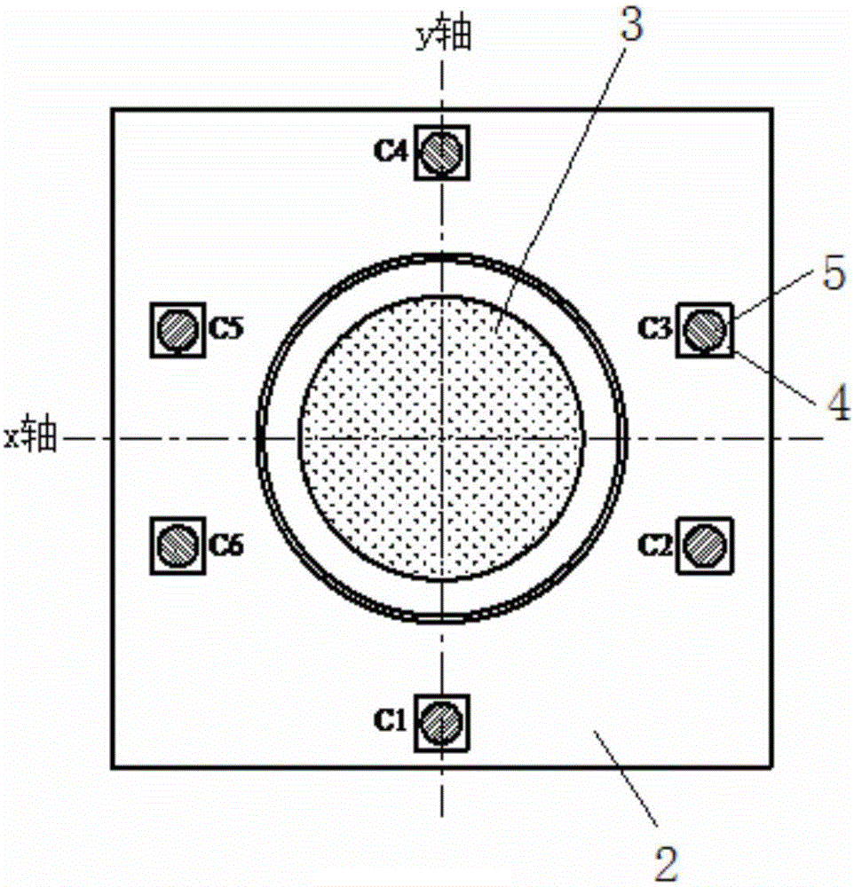
[0022] see figure 2 , the upper part of the testing machine is a spherical hinge structure, in which the spherical hinge head 3 on the lower surface of the spherical hinge support 1 is matched with the spherical groove on the upper surface of the spherical hinge base plate 2 . The vertical axis defining the spherical hinge structure is the z axis, and the two mutually perpendicular axes in the horizontal direction are respectively the x axis and the y axis. In this embodiment, the front-back direction of the experimental operator when facing the testing machine is taken as the y-axis, and the left-right direction is taken as the x-axis.

[0023] The testing machine has a built-in pressure sensor inside, and the built-in pressure sensor is located...

Embodiment 2

[0029] Experiment with the constraint method described in Example 1, by measuring as figure 2 r as shown 1 、r 2 、h 1 、h 2 、h 3 , t, d and other dimensional parameters can be analyzed and obtained. Since the rotation of the testing machine is very small (the rotation angle can be actually measured by the inclinometer 6), the bearing capacity test error caused by this is also very small.

[0030] Take the steel column A experiment as an example.

[0031] The length of steel column A is 3.794 meters, the bearing capacity measured by the built-in sensor of the testing machine is 2826KN, the external pressure sensor measures 56KN, the actual component bears a pressure of 2882KN, the rotation angle of the ball hinge bottom plate is 0.12 degrees, and the reserved gap d=0.8mm .

[0032] It can be seen from the above test results that this method can constrain the upper ball hinge rotation by adding an external pressure sensor without additional lateral constraints, and at the s...


PUM

PropertyMeasurementUnit
lengthaaaaaaaaaa

Abstract

The invention provides a spherical hinge constraining method capable of realizing hinge joint compression on a 1000-t testing machine. According to the method, a built-in pressure sensor is installed in the testing machine and located on a vertical axis of a spherical hinge; a gap between the lower surface of a spherical hinge bearing and the upper surface of a spherical hinge bottom plate is h1; and a plurality of steel plate washers and a plurality of external pressure sensors are arranged in the gap so as to restrict rotation of the spherical hinge bottom plate around an x axis and a y axis. The method cancels erection of an original lateral constraint reaction support on the 1000-t testing machine; rotation of the spherical hinge on the upper part of the testing machine is directly constrained by arranging the external pressure sensors on the spherical hinge bottom plate on the basis of the testing machine; and a knife edge support and other forms are cooperatively used, so ideal hinge joint compression test of members of different lengths is conveniently and reliably realized on the 1000-t long-axis testing machine.

Description

technical field [0001] The invention relates to the technical field of testing machine loading experiments, in particular to a spherical joint constraint method for realizing joint pressure on a 1000t testing machine. Background technique [0002] The 1000t long-axis testing machine (hereinafter referred to as the testing machine) is a test loading device used to test the ultimate bearing capacity of compression members under heavy loads. The top of the testing machine is a spherical joint support (hereinafter referred to as the spherical joint), and the bottom is a cylindrical surface. Hinge bearing (hereinafter referred to as cylindrical hinge). [0003] Since the lower cylindrical hinge of the testing machine can only rotate around the longitudinal axis z of the rod, and cannot realize the function of rotating around the x and y axes of the component section, the cylindrical hinge itself can be regarded as a fixed end under the condition of unidirectional loading; at the ...

Claims


Application Information

Patent Timeline
Patent Type & Authority Applications(China)
IPC IPC(8): G01N3/08
CPCG01N3/08
Inventor 聂诗东杨波熊刚沈乐金声孟凡涛姚万成
Owner CHONGQING UNIV