A high-altitude cable inspection equipment

A high-altitude cable and equipment technology, applied in the field of high-altitude cable inspection equipment, can solve the problems of affecting detection efficiency and low detection efficiency, and achieve the effect of convenient real-time monitoring

Inactive Publication Date: 2018-08-07
STATE GRID SHANDONG ELECTRIC POWER CO LONGKOU POWER SUPPLY CO
View PDF6 Cites 0 Cited by
  • Summary
  • Abstract
  • Description
  • Claims
  • Application Information

AI Technical Summary

Problems solved by technology

[0002] In the existing high-altitude cable inspection process, manual detection is mainly used, the detection efficiency is not high, and there is a certain risk
Some existing inspection robots can perform inspections on some lines, but due to the installation of high-altitude cables, a large number of connectors will be installed, so that inspection robots can only perform segmented inspections during use, which affects detection efficiency

Method used


Image

  • A high-altitude cable inspection equipment
  • A high-altitude cable inspection equipment
  • A high-altitude cable inspection equipment

Examples


Embodiment 1

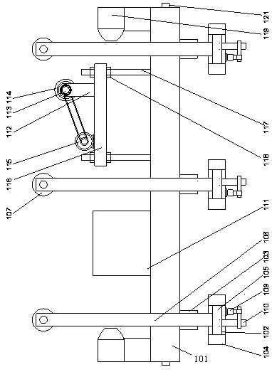
[0021] Such as figure 1 , 2 As shown in , 3, a high-altitude cable inspection equipment includes a base 101 and three moving support plates 102 respectively arranged under the two sides of the base 101, and the width of the moving support plates 102 is larger than that of the base The width of 101, the first hydraulic cylinder 103 is respectively arranged above the two ends of the moving support plate 102, the bottom of the first hydraulic cylinder 103 is fixedly connected to the upper end surface of the moving support plate 102, and the The telescopic rod of the first hydraulic cylinder 103 is fixedly connected to the lower end surface of the base 101, and two flanges 104 are arranged on the side wall of the moving support plate 102, and a rotating shaft is arranged between the flanges 104. 105, the two ends of the rotating shaft 105 are rotatably connected to the flange 104 through bearings, the vertical rod 106 is set on the rotating shaft 105, and the end of the vertical ...

Embodiment 2

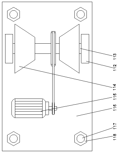
[0026] In this embodiment, in order to facilitate the adjustment of the height of the gear so that it can fit on the cable better, preferably, a lifting plate 116 is arranged on the upper end surface of the base 101, and the lifting plate 116 is provided with a stud 117, the lower end of the stud 117 is fixedly connected to the base 101, the upper end of the stud 117 runs through the lifting plate 116, and the two sides of the lifting plate 116 Adjusting nuts 118 are arranged on the studs 117 respectively, and the motor 115 and the bracket 112 are respectively fixedly connected to the upper end surface of the lifting plate 116 . When needed, turn the adjusting nut to make the stud move longitudinally. During the longitudinal movement of the stud, the lifting plate is driven to move longitudinally, so that the height of the lifting plate can be adjusted, and then the height of the gear can be adjusted so that the gear can fit better. It fits under the cable and is suitable for ...

Embodiment 3

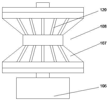
[0029]In order to increase the friction between the gear and the cable and make the overall structure more reliable, in this embodiment, preferably, the gears 114 are two symmetrically arranged on the fixed shaft 113, two The gears 114 are arranged symmetrically below the two sides of the cable.

[0030] In order to make the gear fit better on the cable, in this embodiment, further preferably, the gear 114 is a straight bevel gear. Fit the straight bevel gear under the sides of the cable.


PUM


Abstract

The invention discloses aerial cable inspection equipment. The aerial cable inspection equipment comprises a base and three movable support plates arranged below both sides of the base respectively, wherein the widths of the movable support plates are greater than the width of the base; first hydraulic cylinders are arranged above two ends of the movable support plates respectively; the bottoms of the first hydraulic cylinders are fixedly connected to upper end faces of the movable support plates; telescopic rods of the first hydraulic cylinders are fixedly connected to a lower end face of the base; side walls of each of the movable support plates are provided with two flanges; revolving shafts are arranged between every two flanges; the two ends of the revolving shafts are rotationally connected to the flanges through bearings; vertical rods sleeve the revolving shafts; rollers are arranged at one ends, which are far away from the revolving shafts, of the vertical rods; middle parts of the rollers are depressed towards inner sides, thereby forming V-shaped grooves; and the rollers can be hung on a cable. Through adoption of the aerial cable inspection equipment, an integral structure can cross barriers to realize continuous detection along the length direction of the cable when the aerial cable inspection equipment encounters the barriers.

Description

technical field [0001] The invention relates to high-altitude cable inspection equipment. Background technique [0002] In the existing high-altitude cable inspection process, manual inspection is mainly used, and the detection efficiency is not high, and there is a certain risk. Some existing detection robots can perform inspections on some lines, but due to the installation of high-altitude cables, a large number of connectors will be installed, so that inspection robots can only perform segmented inspections during use, which affects detection efficiency. Contents of the invention [0003] The purpose of the present invention is to provide a high-altitude cable inspection equipment, which can improve the problems existing in the prior art. When an obstacle is encountered, the overall structure can be passed over the obstacle, and continuous detection can be realized along the length direction of the cable, which is convenient for inspection. check. [0004] The presen...

Claims


Application Information

Patent Timeline
Patent Type & Authority Patents(China)
IPC IPC(8): H02G1/02
CPCH02G1/02
Inventor 韩宝益姜绪政王耀庭孟令举陈培军王桐庆刘秉欣龚立军张明新徐东于海
Owner STATE GRID SHANDONG ELECTRIC POWER CO LONGKOU POWER SUPPLY CO
Why Eureka
Try Eureka