Robotic control of imaging devices with optical shape sensing

一种机器人、中成像的技术,应用在医学仪器领域,能够解决组织损伤等问题

Inactive Publication Date: 2016-09-07
KONINKLJIJKE PHILIPS NV
View PDF4 Cites 6 Cited by
  • Summary
  • Abstract
  • Description
  • Claims
  • Application Information

AI Technical Summary

Problems solved by technology

Also, in laparoscopic surgery, equipment can be out of the field of view, which can cause tissue damage when the operator requires visual feedback of the operating site

Method used


Image

  • Robotic control of imaging devices with optical shape sensing
  • Robotic control of imaging devices with optical shape sensing
  • Robotic control of imaging devices with optical shape sensing

Examples


Embodiment Construction

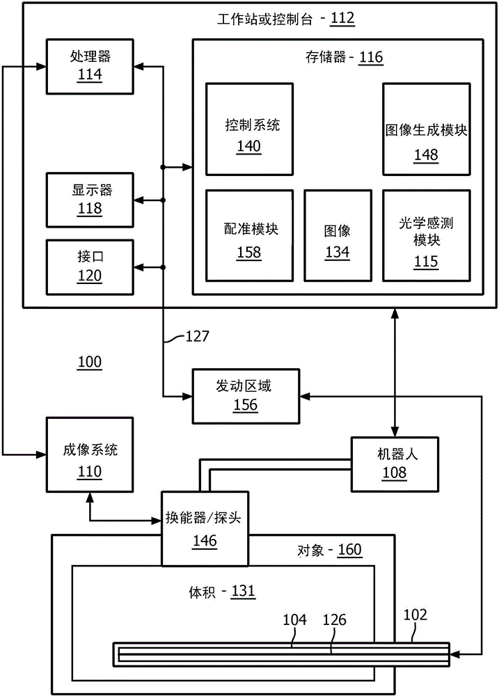
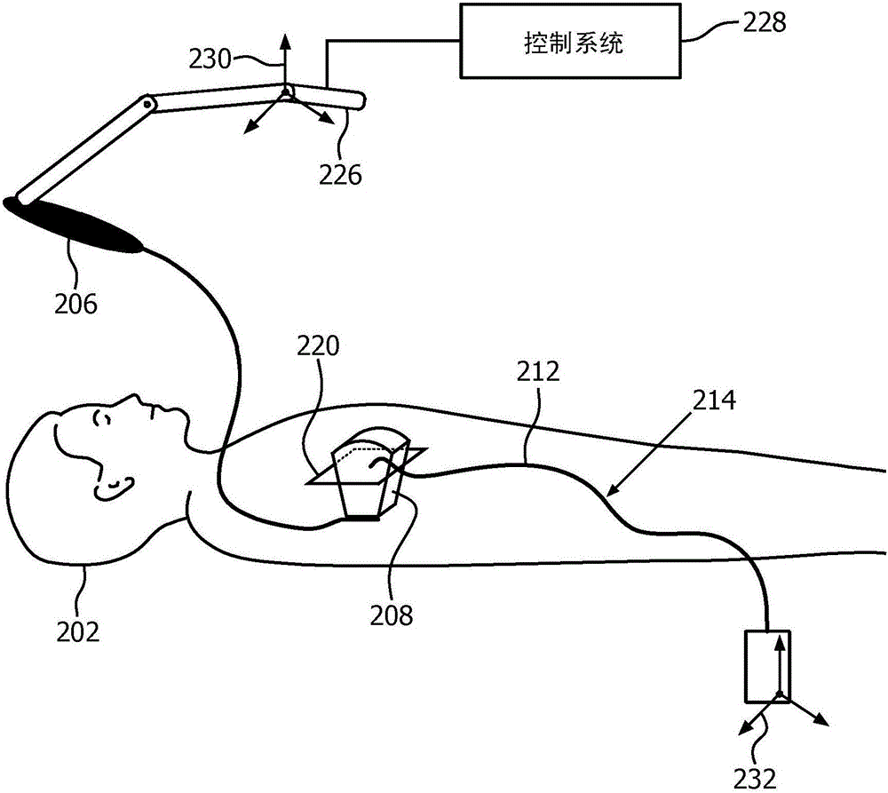
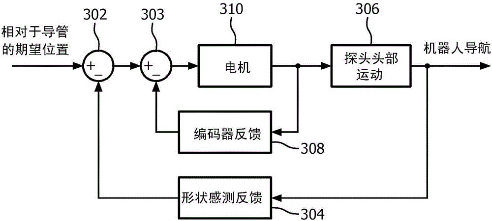
[0016] In accordance with the present principles, systems, devices, and methods are described that provide control of robots using optical shape sensing technology. Image guidance of robotically controlled imaging devices solves the aforementioned mapping problem by allowing the operator to select a target from the most intuitive frame (the image frame). According to the present principles, robotic control of an ultrasound probe is provided to intelligently track an optical shape sensing (OSS) enabled catheter or other device. A system and method are provided to visualize devices during medical procedures by sensing the shapes of the devices, registering the shapes with a robot coordinate frame, and guiding a robot to bring those devices into the field of view of an imaging device. The present principle allows repositioning of the imaging device to reach targets that are not visible in the current view.

[0017] An optical shape sensing interventional device can be used to cl...


PUM


Abstract

A system for tracking a device image includes an intraoperative imaging system (110) having a probe (146) configured to generate an image for a region. A shape sensing enabled instrument (102) is configured to have a portion of the shape sensing enabled instrument positionable relative to the region. The shape sensing enabled instrument has a coordinate system registered with a coordinate system of the intraoperative imaging system. A robot is configured to coordinate movement between the probe and the shape sensing enabled instrument such that movement of the shape sensing enabled instrument relative to the region causes the probe to be moved to maintain the shape sensing enabled instrument within the image.

Description

technical field [0001] The present disclosure relates to medical instrumentation, and more particularly to robotic control systems and methods using optical shape sensing technology. Background technique [0002] Robotic control of real-time imaging devices, such as ultrasound imaging or any type of optical imaging, aims at simplifying the positioning of imaging devices during surgical and interventional procedures. The operator is allowed to perform remote control or image-based control of the equipment. [0003] A disadvantage of remote control using traditional input devices (eg, joysticks) is that the mapping of the robot coordinate system and the coordinate system of the imaging device to the output image is not explicitly known to the operator. This mapping is typically learned during the process and can result in extended operating times. [0004] Image guidance has other problems. These issues can include image guidance being able to track targets that are only wi...

Claims


Application Information

Patent Timeline
Patent Type & Authority Applications(China)
IPC IPC(8): A61B34/30
CPCA61B34/30A61B34/32A61B2034/2061A61B2034/301A61B2090/378A61B2090/3784A61B8/12A61B34/20A61B90/37
Inventor D·P·努南M·L·弗莱克斯曼A·波波维奇
Owner KONINKLJIJKE PHILIPS NV
Why Eureka
Try Eureka