Quick clamp assembling mechanism for grinding wheel

A technology of assembling mechanism and grinding wheel, which is applied to the device for fixing grinding wheel, parts of grinding machine, metal processing equipment, etc. It can solve the problem of cumbersome replacement and achieve the effect of stable positioning and quick replacement of grinding wheel.

Active Publication Date: 2016-09-21
武义史夫克工具股份有限公司
View PDF5 Cites 7 Cited by
  • Summary
  • Abstract
  • Description
  • Claims
  • Application Information

AI Technical Summary

Problems solved by technology

The above replacement is cumberso

Method used


Image

  • Quick clamp assembling mechanism for grinding wheel
  • Quick clamp assembling mechanism for grinding wheel
  • Quick clamp assembling mechanism for grinding wheel

Examples


Example Embodiment

[0018] The following are specific embodiments of the present invention in conjunction with the accompanying drawings to further describe the technical solutions of the present invention, but the present invention is not limited to these embodiments.

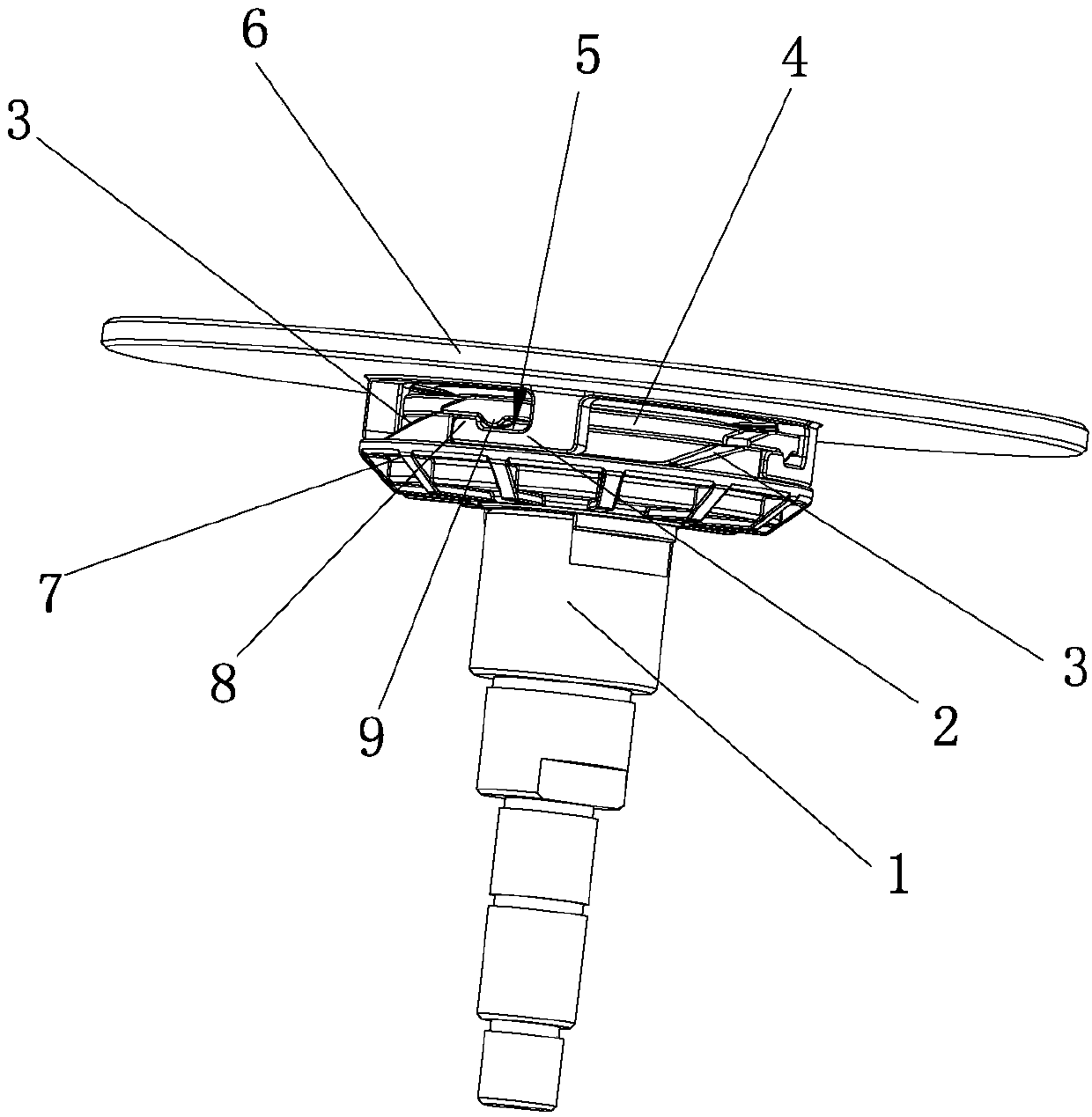
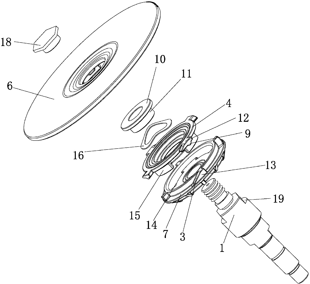
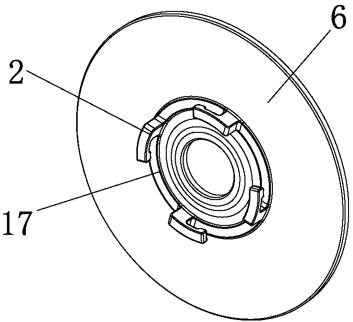
[0019] figure 1 As shown, the present invention includes a mounting seat and a connecting plate 17, the mounting seat is inserted into the output shaft 1 of the electric tool, the output shaft 1 has its own side groove 19, and the mounting seat is blocked by the side groove 19 and cannot rotate. , The end of the output shaft 1 is provided with a nut 18, and the nut 18 fastens the mounting seat on the output shaft 1, and the connecting disc 17 is fixed on one side of the grinding wheel 6.

[0020] figure 1 , 2 As shown, the mounting seat includes a circular chassis 7, a positioning disk 4, a central fastener 11 and a wave disc spring 16. The chassis 7 is provided with a number of limit blocks 13 in a circular array on the edge, and the ...


PUM


Abstract

The invention provides a quick clamp assembling mechanism for a grinding wheel and belongs to the technical field of electric tools. The quick clamp assembling mechanism comprises a discoidal mounting base and a connecting plate, wherein the mounting base is inserted into an output shaft of the electric tool and is limited; a plurality of clamping grooves forming an annular array are formed in the mounting base; the connecting plate is fixed on one surface of the grinding wheel; clamping claws which correspond to the clamping grooves and form an annular array are arranged on the connecting plate; and when the clamping claws are connected with the corresponding clamping grooves, a trip preventing device is also arranged for fastening the clamping grooves and the clamping claws. According to the device, the aim of quickly replacing and clamping the grinding wheel is achieved; in addition, the quick clamp assembling mechanism is suitable for all electric tools using the grinding wheels; and during replacement and clamping, the clamping claws are twisted into the corresponding clamping grooves to realize the positioning, and the stability in positioning is realized.

Description

technical field [0001] The invention belongs to the technical field of electric tools, in particular to a quick-clamp assembly mechanism for a grinding wheel. Background technique [0002] When replacing the existing grinding wheel, one hand first inserts the open-end wrench into the open-end wrench fixing surface on the output shaft, so that the output shaft cannot rotate, and the other hand presses the claw head of the claw wrench into the claw hole of the upper platen, Turn the claw wrench firmly to remove the upper pressure plate; after replacing the grinding wheel, install the upper pressure plate into the upper pressure plate fixing thread of the output shaft, then press the claw head of the claw wrench into the claw hole of the upper pressure plate, and turn the claw forcefully. A wrench is used to tighten the upper platen; both hands are required to remove or install the grinding wheel. The above replacement is more cumbersome and needs to be fixed by screws. Cont...

Claims


Application Information

Patent Timeline
IPC IPC(8): B24B45/00
CPCB24B45/006
Inventor 周俐翔
Owner 武义史夫克工具股份有限公司
Why Eureka
Try Eureka