Rod material cutting machine

A cutting machine and material technology, which is applied to shearing devices, accessories of shearing machines, shearing machine equipment, etc., can solve the problems of inconvenient rotary cutting processing of rod-shaped materials, and achieve the effect of convenient rotary cutting processing.

Inactive Publication Date: 2016-09-28
苏州市灵通玻璃制品有限公司
View PDF12 Cites 0 Cited by
  • Summary
  • Abstract
  • Description
  • Claims
  • Application Information

AI Technical Summary

Problems solved by technology

The cutting machine is inconvenient for rotary cutting of rod-shaped materials

Method used


Image

  • Rod material cutting machine

Examples


Embodiment Construction

[0012] In order to make the technical means, creative features, goals and effects achieved by the present invention easy to understand, the present invention will be further described below in conjunction with specific embodiments.

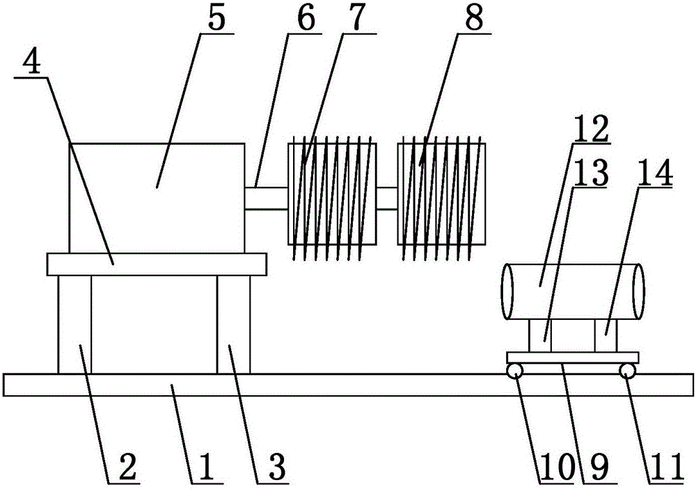
[0013] Such as figure 1 As shown, a rod-shaped material cutting machine includes a bottom plate 1, a first support plate 2 and a second support plate 3 are arranged on the bottom plate 1, the first support plate 2 and the second support plate 3 are vertically arranged, and the first support plate A loading plate 4 is arranged between the end of the plate 2 and the second support plate 3, a driving motor 5 is arranged on the loading plate 4, the driving motor 5 is connected with a driving shaft 6, and one end of the driving shaft 6 is connected with the driving motor 5 The other end of the drive shaft 6 is provided with a first rotary cutter 7 and a second rotary cutter 8, the first rotary cutter 7 and the second rotary cutter 8 have the same shape...


PUM


Abstract

The invention discloses a rod material cutting machine. The rod material cutting machine comprises a base plate. The base plate is provided with a first supporting plate and a second supporting plate. A carrying plate is arranged between the end of the first supporting plate and the end of the second supporting plate. The carrying plate is provided with a driving motor, and the driving motor is connected with a driving shaft. One end of the driving shaft is connected with the driving motor, and a first rotary-cutting wheel and a second rotary-cutting wheel are arranged at the other end of the driving shaft. The first rotary-cutting wheel and the second rotary-cutting wheel are the same in shape and size, and rotary-cutting teeth are arranged on the outer circumferential face of the first rotary-cutting wheel and the outer circumferential face of the second rotary-cutting wheel. The base plate is provided with a movable base. First moving wheels and second moving wheels are arranged at the bottom of the movable base. The first moving wheels and the second moving wheels are arranged on the base plate. The base plate is provided with guide grooves, and the first moving wheels and the second moving wheels are arranged in the guide grooves. The movable base is provided with a guide pipe. By means of the rod material cutting machine, a rod material to be treated can be moved along the guide pipe, and therefore the rod material can be rotary-cut conveniently.

Description

technical field [0001] The invention relates to a cutting machine, in particular to a rod-shaped material cutting machine. Background technique [0002] In the prior art, such as patent ZL201210371551.X discloses a cutting machine for cutting workpieces, the cutting machine includes: a workbench with a workbench support surface supporting the workpiece, a longitudinal edge arranged on the workbench a long extended cutting groove; a corner bracket, rotatably connected to the workbench around the axis of the longitudinal axis, and the axis of the longitudinal axis is flush with the supporting surface of the workbench; a cutting unit, rotatably connected to the workbench around the axis of the pivot axis On the corner bracket, the cutting unit includes a fixed shield rotatably connected to the corner bracket, a motor housing connected to the fixed shield, and a motor accommodated in the motor housing to drive the saw blade to rotate, The saw blade extends at least partially in...

Claims


Application Information

Patent Timeline
Patent Type & Authority Applications(China)
IPC IPC(8): B23D19/00B23D33/02
CPCB23D19/00B23D33/02
Inventor 陆志文
Owner 苏州市灵通玻璃制品有限公司
Why Eureka
Try Eureka