
Cable Retractable System

A cable and cable storage technology, which is applied in the direction of function indication, thin material handling, transportation and packaging, etc., can solve the problem that the cable retracting and unwinding system cannot accurately control the cable pitch, and achieve large starting torque, wide speed regulation range, The effect of smooth stepless speed regulation

Inactive Publication Date: 2017-07-04
HARBIN ENG UNIV
View PDF5 Cites 0 Cited by
  • Summary
  • Abstract
  • Description
  • Claims
  • Application Information

AI Technical Summary

Problems solved by technology

[0003] The purpose of the present invention is to provide a cable retracting system to solve the problem that the cable retracting system in the prior art cannot accurately control the cable pitch

Method used


Image

  • Cable Retractable System
  • Cable Retractable System
  • Cable Retractable System

Examples


specific Embodiment 1

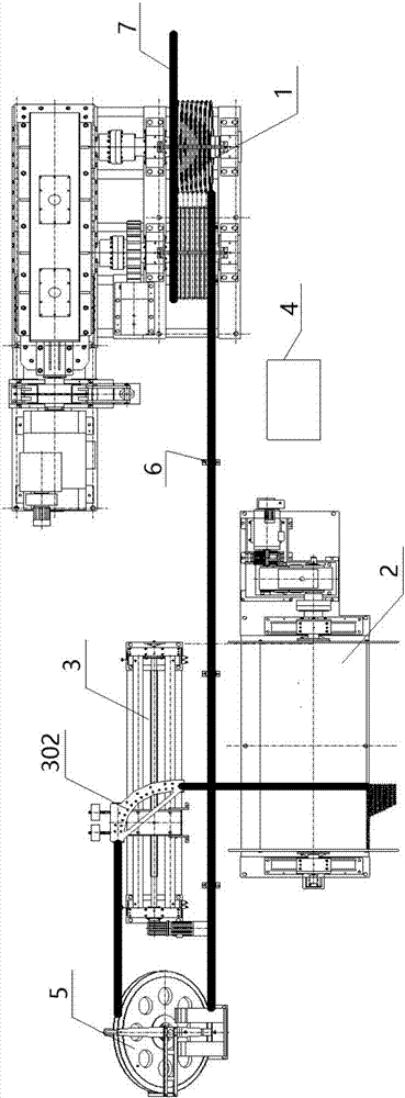
[0037] Such as figure 1 As shown, the present invention provides a cable retracting system, including a traction device 1 fixed on a base 9, a cable storage device 2, a cable discharge device 3 and a control device 4, wherein:

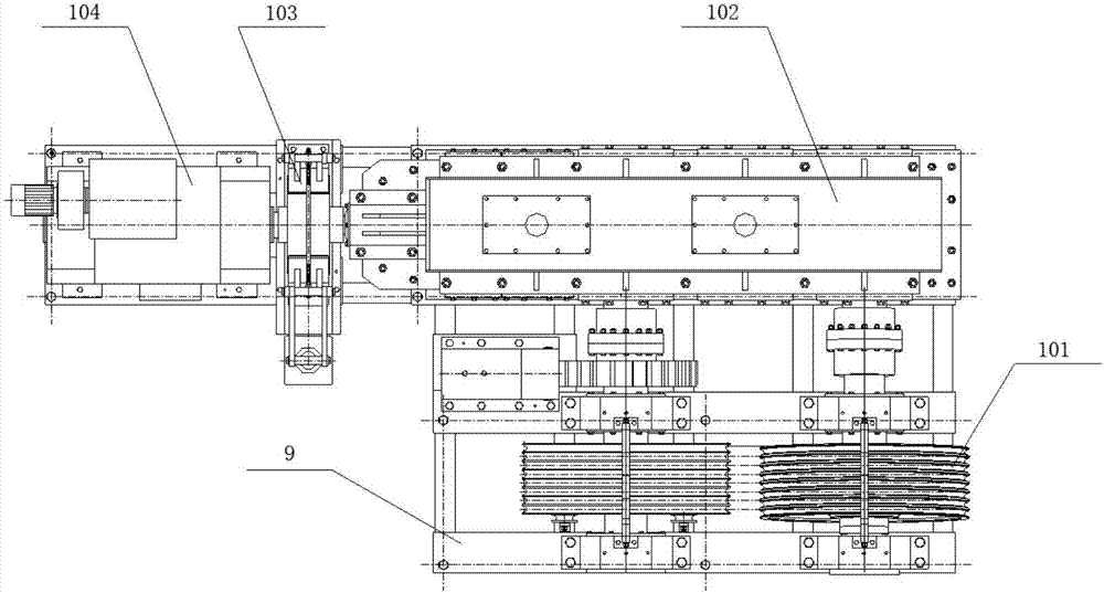
[0038] Such as image 3 As shown, the traction device 1 includes a traction motor 104, a shaft coupling, a traction motor reducer 102, a traction wheel 101, and a traction motor brake 103 located on the base 9; 102 is connected to provide traction power to the traction motor reducer 102, and after deceleration, the traction power is distributed to the traction wheel 101; the traction wheel 101 is used to complete the retraction of the cable 7; The motor brake 103 is connected, and the traction motor brake 103 brakes the traction motor;

[0039] Such as Figure 4 As shown, the cable storage device 2 includes a cable storage motor 201 on the base 9, a cable storage barrel 204, a cable storage motor reducer 203, and a cable storage motor brake 202; the...

specific Embodiment 2

[0059] The cable retracting device for large moored boats is generally fixed in the ground shelter, and is used for the lift-off, parking and recovery operations of the moored boat. The mooring boat is evacuated by cable traction, and the mooring cables are wound on the cable storage barrel in an orderly manner during recovery. Since the net buoyancy of large moored boats generally reaches 2-3t, the maximum tension of the moored cables can reach 14t under the condition of 35m / s wind speed in the air. Under certain conditions, it must also be safe and reliable, including the status of resident, lift-off and recovery.

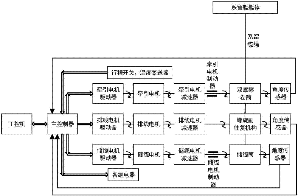
[0060] Such as Image 6 As shown, the embodiment of the present invention provides a system for retracting and unwinding cables. The industrial computer performs tasks such as sending control commands such as cable retracting and unwinding, online monitoring, and data storage through the human-computer interaction interface. The industrial computer is connected...


PUM


Abstract

The invention provides a cable take-up and pay-off system. A cable storage angle sensor traces the change of the rotating amount of a cable storage barrel and sends the change to a main controller; the main controller sends a corresponding control instruction to a cable discharge motor driver according to the change of the rotating amount of the cable storage barrel; the cable discharge motor driver receives the control instruction sent by the main controller and controls a cable discharge motor to provide the change of cable discharge power for a cable discharge motor reducer; therefore, the power provided for a screw rod by the cable discharge motor reducer is also changed due to the change of the cable discharge power; and accordingly the left-right moving distance of a cable discharge frame driven by the screw rod is also changed. According to the cable take-up and pay-off system, under driving of a direct current motor, the moving distance of the cable discharge frame and the change of the rotating amount of the cable storage barrel meet the predetermined corresponding relationship, that is, in the working state, the cable storage barrel rotates by one circle, the cable discharge frame walks by one pitch along a screw pair reciprocating mechanism, and the cable discharge pitch is precisely controlled.

Description

technical field [0001] The invention relates to the technical field of cable retraction, in particular to a cable retraction system. Background technique [0002] The cable retracting system is used to control the release, recovery and braking of the cable. The traction motor used in the prior art is an AC motor, and a frequency converter is used to control the speed of the AC motor; the cable storage process uses an AC motor to drive the cable storage drum, and the proportional-integral-derivative control algorithm is used to control the output of the frequency converter to adjust the cable. Tension; The cable unwinding process is driven by a stepper motor, and the synchronization between the cable unwinding system and the cable storage drum is realized through the open-loop control of the stepper motor. The cable-discharging process requires the cable-discharging frame to accurately control the cable-discharging pitch, and the pitch control accuracy of the prior art canno...

Claims


Application Information

Patent Timeline
Patent Type & Authority Patents(China)
IPC IPC(8): B65H75/44
CPCB65H75/4405B65H75/4486B65H2511/21B65H2515/32B65H2701/35B65H2220/01B65H2220/02
Inventor 张兰勇刘泽威刘胜李冰刘洪丹
Owner HARBIN ENG UNIV
Learn More