Telescopic bracket
A telescopic bracket and telescopic rod technology, applied in the direction of lifting frame, lifting device, etc., can solve the problem of easy vibration, and achieve the effect of improving shock absorption and preventing shaking.
- Summary
- Abstract
- Description
- Claims
- Application Information
AI Technical Summary
Problems solved by technology
Method used
Image

Examples
Embodiment Construction
[0010] In order to make the object, technical solution and advantages of the present invention clearer, the present invention will be further described in detail below in conjunction with the accompanying drawings and embodiments. It should be understood that the specific embodiments described here are only used to explain the present invention, not to limit the present invention.
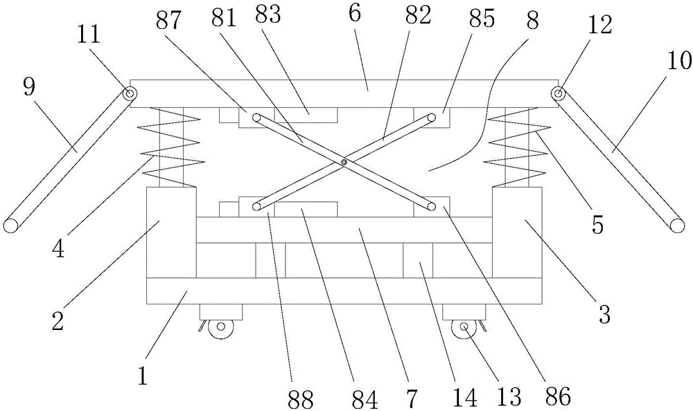
[0011] see figure 1 , figure 1 It is a structural schematic diagram of the present invention.
[0012] The telescopic support includes a base plate 1, a telescopic rod A2 and a telescopic rod B3 are installed above the base plate 1, a spring A4 is installed above the telescopic rod A2, and a spring A4 is installed above the telescopic rod B3. A spring B5 is installed, and a placement plate 6 for placing packaging machinery is installed on the upper ends of the telescopic rod A2 and the telescopic rod B3, and a support plate 7 is installed between the telescopic rod A2 and the telescopic rod B3. ...
PUM
 Abstract
Description
Claims
Application Information