
Rigidity-improved spherical hinge and method for improving rigidity of spherical hinge

A ball joint and stiffness technology, applied in the field of improving the stiffness of the ball joint, can solve the problems of large space occupation, heavy product, large strain, etc., and achieve the effect of improving stiffness and fatigue resistance, improving fatigue resistance, and increasing stiffness

Inactive Publication Date: 2016-09-28
ZHUZHOU TIMES NEW MATERIALS TECH
View PDF9 Cites 11 Cited by
  • Summary
  • Abstract
  • Description
  • Claims
  • Application Information

AI Technical Summary

Problems solved by technology

[0005] 1. Increase the rigidity by increasing the volume of the product. This method takes up a lot of space, the product is too heavy, and the installation is troublesome. It may also cause the position and size of the associated components to be modified;
[0006] 2. The rubber layer is made of a rubber material with high hardness. This method will cause a large strain of the product and the fatigue resistance of the product is not ideal
And the application number is CN201010129020.0 the outer surface of the mandrel in the invention patent except the main arc section is also provided with the concave arc section connected with the main arc section, but the main arc section and the concave arc section of this patent There is no convex arc segment between the arc segments, and its stiffness characteristics are different from those of the present invention

Method used


Image

  • Rigidity-improved spherical hinge and method for improving rigidity of spherical hinge
  • Rigidity-improved spherical hinge and method for improving rigidity of spherical hinge
  • Rigidity-improved spherical hinge and method for improving rigidity of spherical hinge

Examples


Embodiment 1

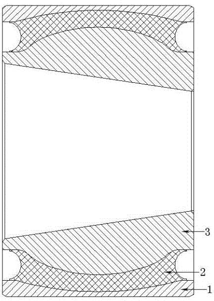
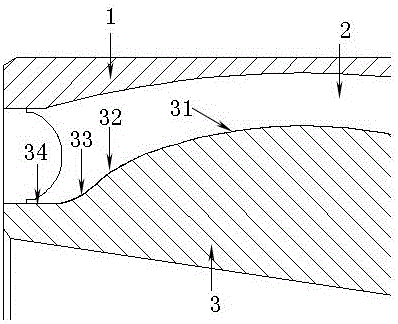
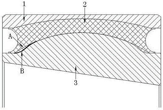
[0031] Such as figure 1 and figure 2 As shown, the outer casing 1, the rubber layer 2 and the mandrel 3 of the ball joint are all rotating bodies, the outer casing 1 and the mandrel 3 are metal parts, and the outer casing 1, the mandrel 3 and the rubber layer 2 are vulcanized together. The peripheral surface of the mandrel 3 includes a main arc segment 31 , an outer convex arc segment 32 , an inner concave arc segment 33 and an annular straight segment 34 . Both sides of the main arc section 31 are provided with two outwardly convex arc sections 32 , but the arc radius of the outwardly convex arc section 32 is smaller than that of the main arc section 31 . The outer side of the convex arc segment 32 is provided with an inner concave arc segment 33 which is concave inward, and the outer side of the inner concave arc segment 33 is also provided with an annular straight segment 34 .

[0032] Wherein the main circular arc section 31, the convex circular arc section 32 and the c...


PUM


Abstract

A rigidity-improved spherical hinge comprises a rubber layer, a mandrel and an outer cover. Outward-protruding circular-arc sections protruding towards the outer side are arranged on the two sides of a main circular-arc section of the periphery of the mandrel, the circular-arc radius of the outward-protruding circular-arc sections is smaller than that of the main circular-arc section, and inward-concave circular-arc sections concaved towards the inner side are arranged on the outer sides of the outward-protruding circular-arc sections. The outward-protruding circular-arc sections protruding towards the outer side are cut on the two sides of the main circular-arc section of the mandrel, the inward-concave circular-arc sections concaved towards the inner side are cut on the outer sides of the outward-protruding circular-arc sections, and thus the structure of the rubber layer vulcanized on the mandrel is changed accordingly. The rigidity of the spherical hinge is improved by changing the structures of the mandrel and the rubber layer in the spherical hinge. The dimension of an opening of the spherical hinge is increased due to the outward-protruding circular-arc sections and the inward-concave circular-arc sections; besides, the main circular-arc section, the outward-protruding circular-arc sections and the inward-concave circular-arc sections are in smooth transition so that the strain of the rubber layer can be effectively reduced, and thus the anti-fatigue performance and the stability of the product can be improved.

Description

technical field [0001] The invention relates to a method and a product for improving the rigidity of a ball joint, in particular to a method and a product for improving the rigidity of a ball joint by improving the structures on both sides of the mandrel and the rubber layer in the ball joint. Background technique [0002] The ball joint is a commonly used rubber-metal composite vibration damping and connecting element. Its main function is to connect the car body and the frame, which can transmit force and provide multi-directional cushioning elements. The metal parts and rubber are vulcanized into a whole under certain temperature and pressure through the adhesive. [0003] In the existing spherical hinge products, generally single arc design is adopted. With the advancement of science and technology, the radial stiffness of the spherical hinge is required to be larger and larger, while the torsional stiffness of the product remains unchanged. This design at this stage ha...

Claims


Application Information

Patent Timeline
Patent Type & Authority Applications(China)
IPC IPC(8): F16C11/06B29C65/64F16F1/387F16F15/08
CPCF16C11/0604F16C11/0661F16C11/0685F16F1/387F16F15/08
Inventor 颜瑶荣继刚林立钿冯万盛
Owner ZHUZHOU TIMES NEW MATERIALS TECH
Learn More