Expansion valve, refrigerant cycle system and air conditioner

A technology of expansion valve and valve needle, which is applied in the direction of refrigeration and liquefaction, fluid circulation arrangement, valve lift, etc., to achieve the effect of reducing throttling

Inactive Publication Date: 2016-09-28
GREE ELECTRIC APPLIANCES INC
View PDF7 Cites 11 Cited by
  • Summary
  • Abstract
  • Description
  • Claims
  • Application Information

AI Technical Summary

Problems solved by technology

[0003] The object of the present invention is to provide an expansion valve, a refrigerant circulation system and an air conditioner, so as to improve the problem that the expansion valve in the prior art still has a throttling effect when it is fully open.

Method used


Image

  • Expansion valve, refrigerant cycle system and air conditioner
  • Expansion valve, refrigerant cycle system and air conditioner
  • Expansion valve, refrigerant cycle system and air conditioner

Examples


Embodiment 1

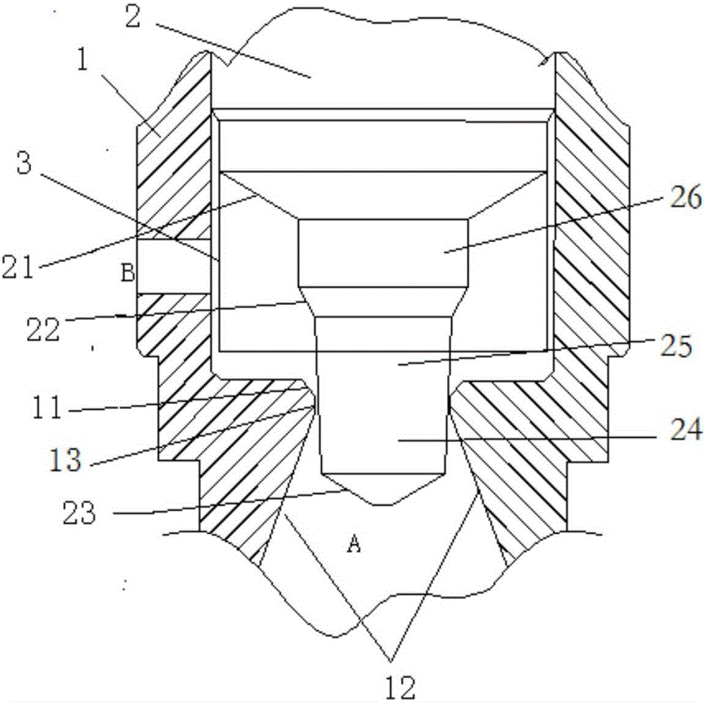
[0036] Such as figure 2 , 4 As shown in and 5, the expansion valve of this embodiment includes a valve body 1 and a valve needle 2 arranged in the valve body 1, the valve body 1 has a valve needle hole, and the valve needle 2 includes a flow regulating part for inserting into the valve needle hole, The cross section of the flow regulating part is reduced along the flow direction of the fluid in the expansion valve, and the valve needle 2 can move along the axial direction of the needle hole to change the gap between the flow regulating part and the valve needle hole. The flow regulating part Including the first valve needle section 24 and the second valve needle section 25 arranged along the above-mentioned flow direction, the first valve needle section 24 is located downstream of the second valve needle section 25 along the fluid flow direction, the cross section of the first valve needle section 24 The rate of change of is greater than the rate of change of the cross-secti...

Embodiment 2

[0081] Figure 6 A schematic structural diagram of the expansion valve according to the second embodiment of the present application is shown. Such as Figure 6 As shown, the structure of the expansion valve of this embodiment is different from that of Embodiment 1 in that: the valve needle hole includes a first port 12, and the upstream section of the first port 12 along the fluid flow direction in the expansion valve is connected to the equal-diameter section 13 , The equal-diameter section 13 extends to the end of the needle hole. That is to say, the valve needle hole of the present embodiment lacks the second port 11 compared with the valve needle hole of the first embodiment.

Embodiment 3

[0083] Figure 7 A schematic structural diagram of the expansion valve according to the third embodiment of the present application is shown. Such as Figure 7 As shown, the structure of the expansion valve of this embodiment is different from that of Embodiment 1 in that: the end surface of the downstream end of the valve needle 2 along the fluid flow direction in the expansion valve is a plane. That is to say, the valve needle 2 of this embodiment lacks the top 23 compared with the valve needle 2 of the first embodiment.


PUM


Abstract

The invention relates to an expansion valve, a refrigerant cycle system and an air conditioner. The expansion valve comprises a valve body (1) and a valve needle (2) arranged in the valve body (1), the valve body (1) is provided with a valve needle hole, the valve needle (2) is provided with a flow adjusting portion used for being inserted into the valve needle hole, the cross section of the flow adjusting portion is reduced in the flowing direction of fluid in the expansion valve, the valve needle (2) can move in the axial direction of the valve needle hole so as to change a gap between the flow adjusting portion and the valve needle hole, the flow adjusting portion comprises a first valve needle segment (24) and a second valve needle segment (25), the first valve needle segment (24) is located on the downstream portion of the second valve needle segment (25) in the flowing direction of the fluid, the change rate of the cross section of the first valve needle segment (24) is larger than that of the second valve needle segment (25). The expansion valve is beneficial for reducing the throttling function under the full-open state.

Description

technical field [0001] The invention relates to the technical field of refrigeration, in particular to an expansion valve, a refrigerant circulation system and an air conditioner. Background technique [0002] Such as figure 1 As shown, the electronic expansion valve includes a valve body and a fluid inlet pipe 1' and a fluid outlet pipe 2' connected to the valve body. A valve needle and a valve needle hole are arranged inside the valve body, and the valve needle is arranged in the valve needle hole. The valve needle includes a tapered section. When the valve needle moves in the valve needle hole, the gap (opening) between the above-mentioned tapered section and the valve needle hole changes, so that the flow rate of the valve body changes. The flow curve of the electronic expansion valve often changes linearly with the opening degree, and the slope of the whole curve does not change much. When the electronic expansion valve is fully open, the electronic expansion valve sti...

Claims


Application Information

Patent Timeline
Patent Type & Authority Applications(China)
IPC IPC(8): F16K1/38F25B41/06F25B41/31
CPCF16K1/385F25B41/31
Inventor 罗永前熊军吴俊鸿廖敏彭光前
Owner GREE ELECTRIC APPLIANCES INC
Why Eureka
Try Eureka