
a connection structure

A connection structure, threaded through hole technology, applied in the direction of the casing/cover/support, electrical components, electromechanical devices, etc., can solve the problems of difficult disassembly, inconvenient maintenance, poor roundness of the positioning flange 200, etc.

Active Publication Date: 2018-03-30
GREE ELECTRIC APPLIANCES INC +1
View PDF6 Cites 0 Cited by
  • Summary
  • Abstract
  • Description
  • Claims
  • Application Information

AI Technical Summary

Problems solved by technology

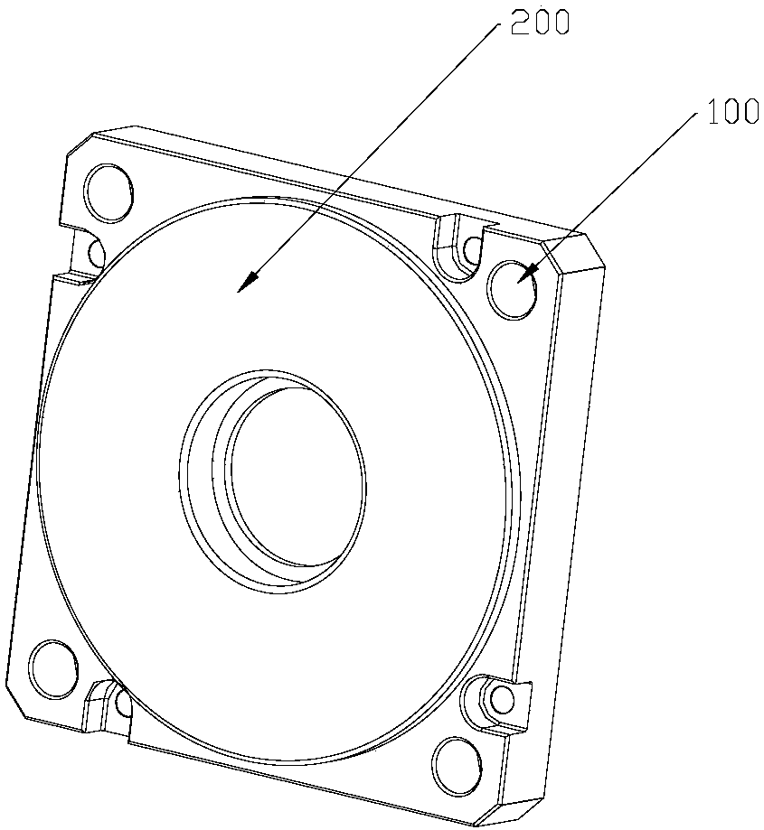
However, during the fixing process, due to the processing quality of the front end cover itself or due to bumps during transportation, it is easy to cause poor roundness of the positioning flange 200 or deformation during transportation, etc., and a large external force is required during installation. Only then can the positioning flange 200 be driven into the corresponding structural parts to achieve positioning
However, if it is necessary to reinstall or replace other motors, it will be difficult to remove the motor
Generally, in this case, methods such as knocking on the front cover with greater force are used, so it is easy to cause damage to the motor.
Therefore, it is difficult to disassemble the current servo motor after installation, and it is very inconvenient to maintain.

Method used


Image

  • a connection structure
  • a connection structure
  • a connection structure

Examples


Embodiment Construction

[0030] In order to further explain the technical means and effects of the present invention to achieve the intended purpose of the invention, the specific implementation, structure, features and effects of the application according to the present invention will be described in detail below in conjunction with the accompanying drawings and preferred embodiments. . In the following description, different "one embodiment" or "embodiment" do not necessarily refer to the same embodiment. Furthermore, the particular features, structures, or characteristics of one or more embodiments may be combined in any suitable manner.

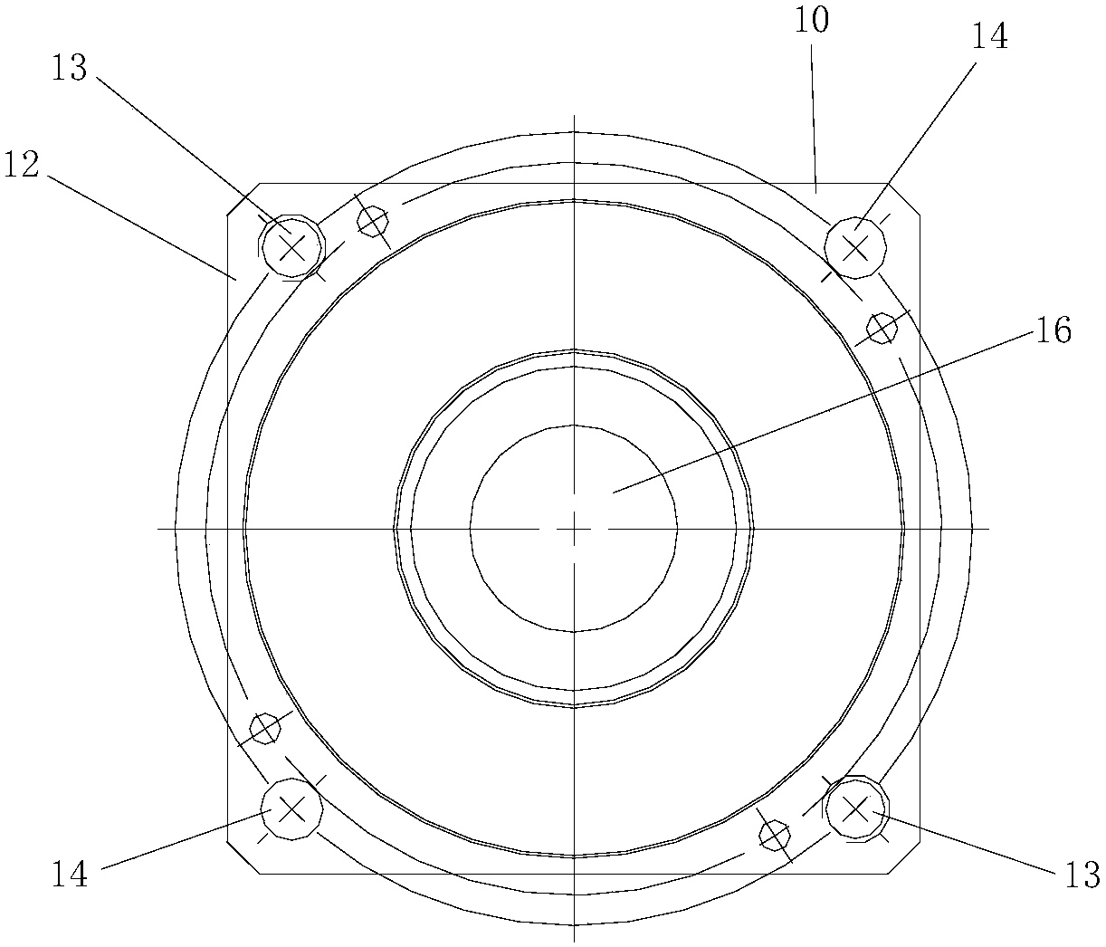
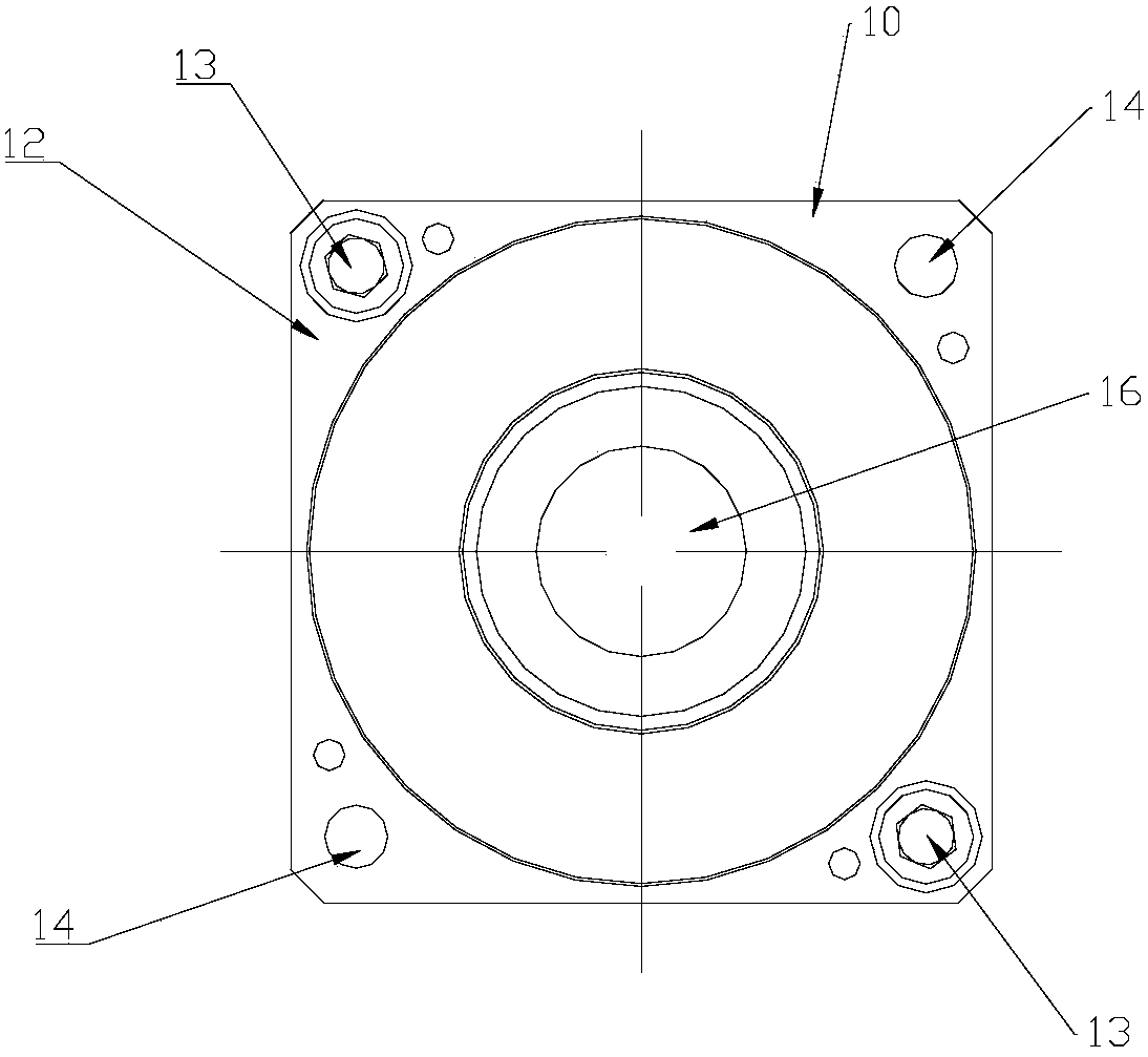
[0031] Such as Figure 2 to Figure 5 As shown, an embodiment of the present invention proposes a connection structure for connecting with an installation surface of an external device, which includes a body 10 , and the body 10 includes a first surface 11 and a second surface 12 disposed opposite to each other. Wherein, the first surface 11 is a surface fixedly...


PUM


Abstract

The invention relates to a connection structure, which is used for being connected with a mounting surface of external equipment. The connection structure comprises a body, wherein the body comprises a first surface and a second surface which are oppositely arranged; the first surface is the surface which is fixedly connected with the mounting surface; a threaded through hole which passes through the second surface is arranged in the first surface and is arranged as follows: after fixed connection of the body and the mounting surface is loosened, the bolt is screwed into the threaded through hole from one side of the second surface and is further tightened when one end of the bolt abuts on the mounting surface; and the first surface is gradually separated from the mounting surface. According to the technical scheme, the connection structure is easy to install and dismantle and convenient to maintain.

Description

technical field [0001] The invention relates to the field of mechanical connection, in particular to a connection structure. Background technique [0002] When the servo motor is installed, it is generally fixed by bolts passing through the four mounting holes 100 on the front end cover and the holes on the corresponding structural parts. The specific structure is as follows: figure 1 shown. However, during the fixing process, due to the processing quality of the front end cover itself or due to bumps during transportation, it is easy to cause poor roundness of the positioning flange 200 or deformation during transportation, etc., and a large external force is required during installation. Only then can the positioning flange 200 be driven into corresponding structural parts to realize positioning. However, if it is necessary to reinstall or replace other motors, there will be a problem of difficulty in taking out the motor. Generally, in this case, methods such as knocki...

Claims


Application Information

Patent Timeline
Patent Type & Authority Patents(China)
IPC IPC(8): H02K5/04
CPCH02K5/04
Inventor 郝福刚赵正李昊钟成堡谢芳李峰岩
Owner GREE ELECTRIC APPLIANCES INC
Learn More