Closing assembly for a blade ring of turbomachinery

A technology of closed components and turbines, applied in the direction of supporting components of blades, engine components, mechanical equipment, etc., can solve the problems of raising the closed component seat, raising tension parts, etc., and achieve long life, economical dismantling and reuse Effect

Inactive Publication Date: 2009-01-21
SIEMENS AG
View PDF6 Cites 13 Cited by
  • Summary
  • Abstract
  • Description
  • Claims
  • Application Information

AI Technical Summary

Problems solved by technology

[0005] The disadvantage here is that the bolts required to raise the tensioner rest on the bottom of the tank
Due to the different thermal expansions of the rotor and closure assembly parts and due to the influence of centrifugal force, the contact of the bolt with the bottom of the groove is suddenly released, so that the fixed closure assembly seat is raised

Method used


Image

  • Closing assembly for a blade ring of turbomachinery
  • Closing assembly for a blade ring of turbomachinery
  • Closing assembly for a blade ring of turbomachinery

Examples


Embodiment Construction

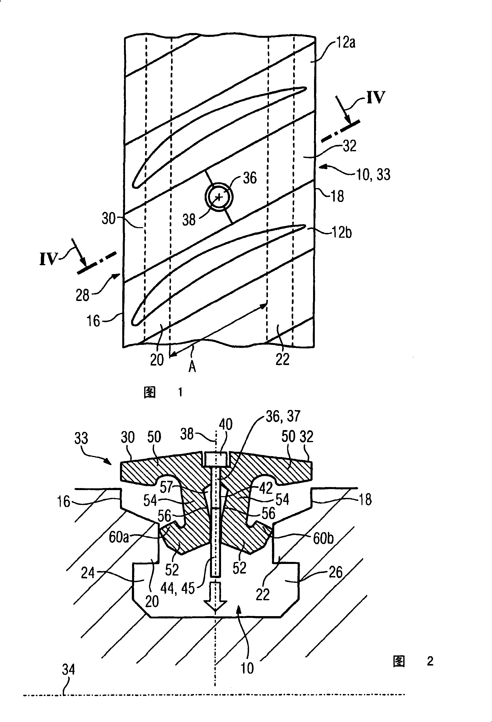
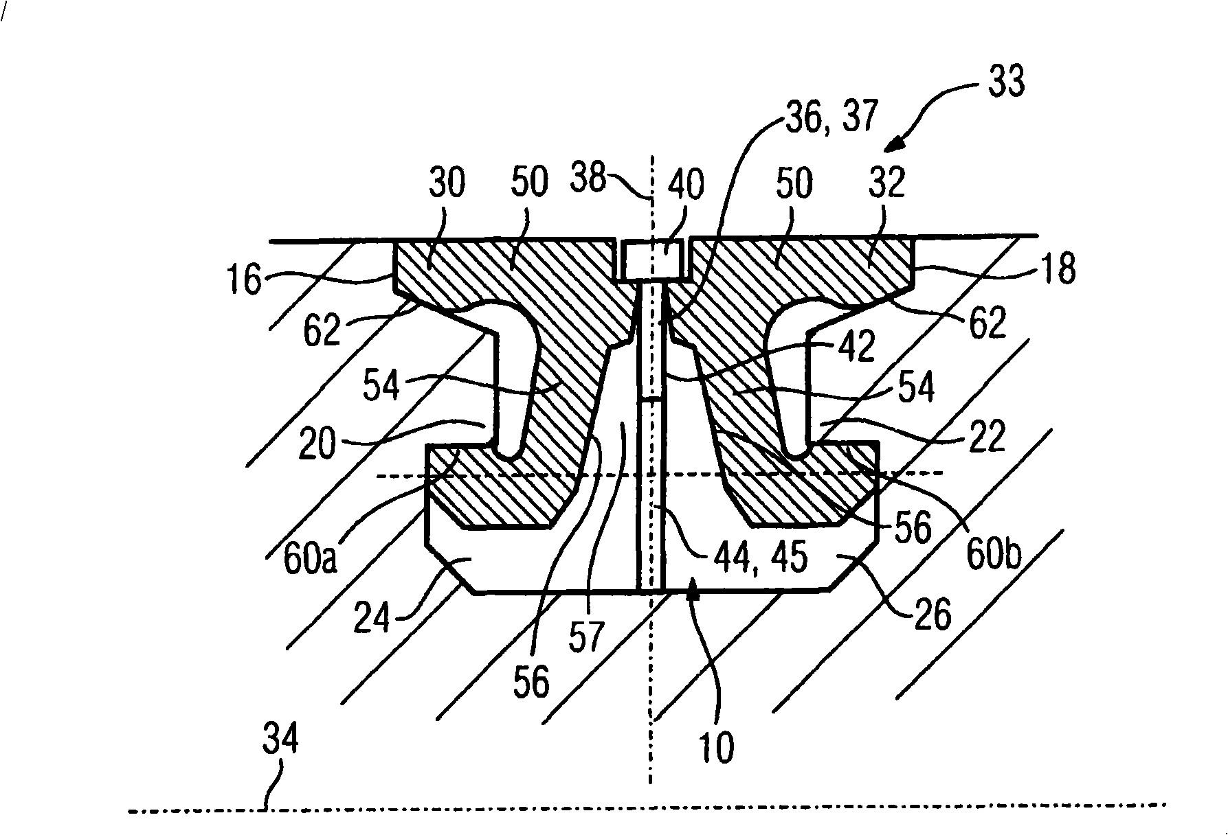
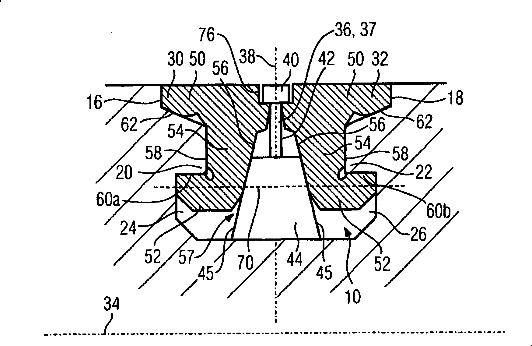
[0029] FIG. 1 shows a section of an annular groove 10 fitted with a turbine blade 12 . An annular groove 10 is provided on the outer surface of the turbine rotor. The ring groove 10 can also be provided on the inner compressor casing of the aircraft turbine, to which the turbine blades are fastened. The annular groove 10 has a front side wall 16 and a rear side wall 18 viewed in the axial direction of the rotor. On these side walls are respectively provided with protrusions 20 and 22 distributed in the circumferential direction and extending in the axial direction, which form the front side respectively. And the undercut position 24,26 (FIG. 2) of the back.

[0030] The working blades 12 a , 12 b are inserted into the ring groove 10 , and the working blades 12 a , 12 b have hammer-shaped blade roots corresponding to the undercuts 24 , 26 . In this case the rotor blades 12 a , 12 b are inserted into the ring groove 10 and then turned so far, for example through 45° or 60°, un...


PUM


Abstract

The invention relates to a closing assembly (33) for closing the gap (28) remaining between the first and last blade (12a, 12b) of a blade ring that is inserted into a peripheral groove (10) of turbomachinery. Said assembly comprises at least two parts (30, 32), each of which can be hooked onto projections (20, 22) that form an undercut (24, 26) in said peripheral groove (10) and comprises a securing element (36), which secures the parts (30, 32) from becoming detached from the peripheral groove (10). To provide a closing assembly (33) for closing the remaining gap (28), which can be simply and cost-effectively detached and which reliably withstands high mechanical stress, the securing element (36) is mounted to rotate about its longitudinal axis (38) between the two parts (30, 32) and has a key head (40) and a web (44). The web (44) of the securing element (32) can be positioned by rotation in such a way that to fit the parts (30, 32) in the peripheral groove (10), said parts can be displaced in relation to one another and to secure the parts (30, 32) from being detached from said groove, (10) the web (44) of the securing element (36) can be placed against at least one lateral face (56) of one of the parts (30, 32).

Description

technical field [0001] The invention relates to a closure assembly for closing the intermediate space remaining between the first blade and the last blade of a blade ring inserted into an annular groove of a turbomachine (Stroemungsmaschine), which has at least two forming The parts hooked by the raised part of the undercut part also has a fastening element that fastens the two parts to prevent them from coming out of the ring groove. Background technique [0002] Closure assemblies of this kind are disclosed, for example, in EP 1457642A2 and US 2002 / 0127105A1. Both closure assemblies basically consist of two side parts which are inserted into the gap remaining between the first and last vanes of the vane ring. Since each of the side parts is hooked separately to a projection forming an undercut of the ring groove and thus allows the two side parts to be inserted into the intermediate space, the two side parts together—viewed in the axial direction—have to be Narrower than...

Claims


Application Information

Patent Timeline
Patent Type & Authority Applications(China)
IPC IPC(8): F01D5/30
CPCF05D2260/30F01D5/32Y02T50/673F01D5/3038Y02T50/60
Inventor J·克鲁茨菲尔特M·孔泽S·-U·马丁S·穆特克钱康C·里克特O·斯奈德P·施罗德M·施瓦茨U·沃尔特克
Owner SIEMENS AG
Why Eureka
Try Eureka