Eureka AIR delivers breakthrough ideas for toughest innovation challenges, trusted by R&D personnel around the world.

Routing method and device based on service transmission

A technology of service transmission and transmission path, which is applied in the field of communication and can solve the problems of low resource utilization and occupation

Active Publication Date: 2016-09-28
CHINA UNITED NETWORK COMM GRP CO LTD
View PDF7 Cites 8 Cited by
  • Summary
  • Abstract
  • Description
  • Claims
  • Application Information

AI Technical Summary

Problems solved by technology

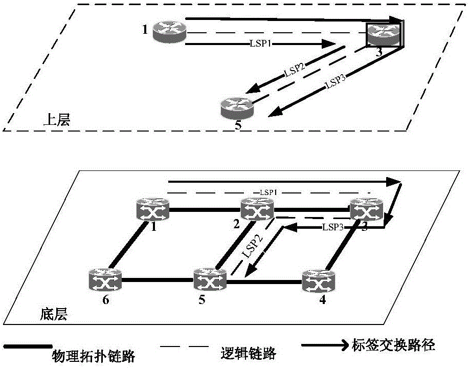
like figure 1 As shown in , LSP3 is a multi-hop LSP established on LSP1 and LSP2. Although it utilizes the existing LSP, since the path of LSP1 is (transport node 1-transport node 2-transport node 3), the path of LSP2 is (transport node 3-transport node 2-transport node 5), so the path of the newly created LSP3 is (transport node 1-transport node 2-transport node 3-transport node 2-transport node 5), obviously the newly-built LSP3 is not a optimal path
However, when there is no request for direct connection to the LSP, DNM directly creates an LSP on the physical topology layer according to the starting node and destination node of the service transmission. Obviously, this solution can obtain a shortest path, but because there is no ready-made LSP Available, so the link needs to be re-established to occupy new wavelength resources, resulting in relatively low resource utilization

Method used


Image

  • Routing method and device based on service transmission
  • Routing method and device based on service transmission
  • Routing method and device based on service transmission

Examples


Embodiment Construction

[0104] The following will clearly and completely describe the technical solutions in the embodiments of the present invention with reference to the accompanying drawings in the embodiments of the present invention. Obviously, the described embodiments are only some, not all, embodiments of the present invention. Based on the embodiments of the present invention, all other embodiments obtained by persons of ordinary skill in the art without creative efforts fall within the protection scope of the present invention.

[0105] In order to clearly describe the technical solutions of the embodiments of the present invention, in the embodiments of the present invention, words such as "first", "second", and "third" are used for the same or similar items with basically the same functions and effects To make a distinction, those skilled in the art can understand that words such as "first", "second", and "third" do not limit the number and execution order.

[0106] An embodiment of the p...


PUM


Abstract

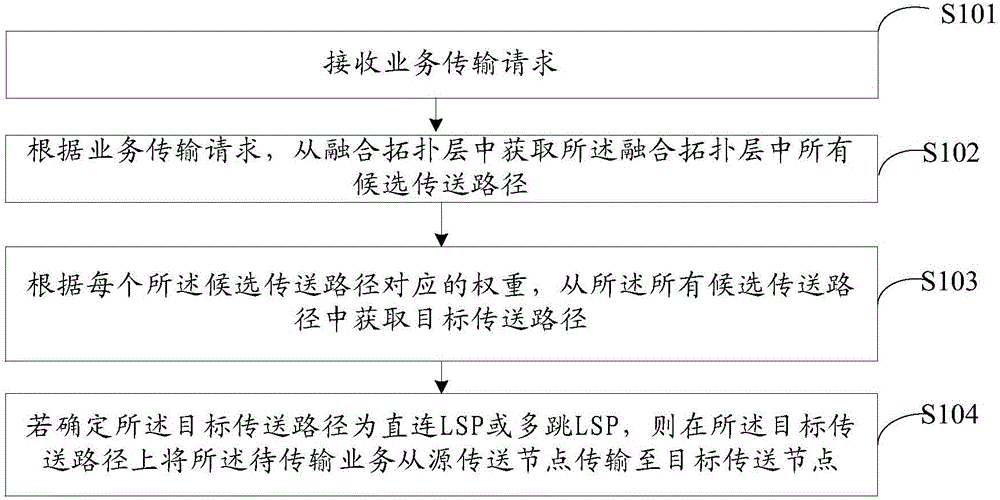
The invention provides a routing method and device based on service transmission, and relates to the field of communication technology. The method and device are used to transmit services in an optimal path, and improve the resource utilization rate in the multi-layer optical network. The method comprises that a service transmission request is received, and according to the service transmission request, all candidate transmission paths of a fused topology layer are obtained from the fused topology layer; according to the weight of each candidate transmission path, a target transmission path, whose weight is lowest, is obtained from all the candidate transmission paths; and whether the target transmission path is a direct-connection LSP or a multi-hop LSP is determined, and a service to be transmitted is transmitted from a source transmission node to a target transmission node in the target transmission path. The routing method and device are applied to the multilayer optical network.

Description

technical field [0001] The embodiments of the present invention relate to the technical field of communications, and in particular, to a method and device for routing based on service transmission. Background technique [0002] In a multilayer optical network based on GMPLS (Generalized Multiprotocol Label Switching) / PCE (Path Computation Element, Path Computation Unit), a multilayer optical network includes two transmission planes, and one transmission plane consists of multiple The two transmission planes are controlled by a unified GMPLS control plane. [0003] Wherein, the switching technology of each transport node interface is identified by its interface switching capability (ISC, Interface Switching Capability), for example, packet switching capability PSC (Packet Switching Capable), wavelength switching capability LSC (Lambda Switching Capable), etc. In this multi-layer optical network, a label switching path (LSP) starts and ends at the same layer, but it may span ...

Claims


Application Information

Patent Timeline
Patent Type & Authority Applications(China)
IPC IPC(8): H04L12/723H04L12/721H04L45/50
CPCH04L45/123H04L45/50
Inventor 张力方胡泽妍陈丹许珺张涛
Owner CHINA UNITED NETWORK COMM GRP CO LTD
Why Eureka
Eureka Blog
Learn More