A main shaft device

A spindle device, the technology of the spindle, which is applied in the directions of large fixed members, metal processing machinery parts, maintenance and safety accessories, etc., can solve problems such as the inability to ensure the reliability of the spindle and the reduction of the recovery space.

Active Publication Date: 2016-10-05
JTEKT CORP
View PDF7 Cites 4 Cited by
  • Summary
  • Abstract
  • Description
  • Claims
  • Application Information

AI Technical Summary

Problems solved by technology

In addition, there is a possibility that the recovery space of the fluid of the hydrostatic bearing becomes small, and the reliability of the rotation of the main shaft cannot be ensured.

Method used


Image

  • A main shaft device
  • A main shaft device
  • A main shaft device

Examples


Embodiment Construction

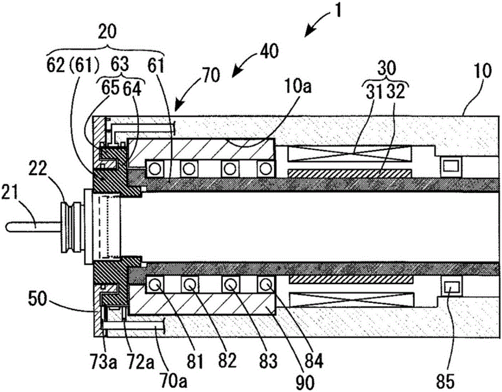
[0020] Hereinafter, a first embodiment of a spindle device according to the present invention will be described with reference to the drawings. For the structure of the spindle device, refer to figure 1 Be explained. Such as figure 1 As shown, the spindle device 1 includes a housing 10, a spindle 20, a motor 30, a support device 40, and a cover 50 (corresponding to a shielding member). In addition, in the description of the spindle device 1, the figure 1 The left side is called the front side, and the figure 1 The right side is called the posterior side.

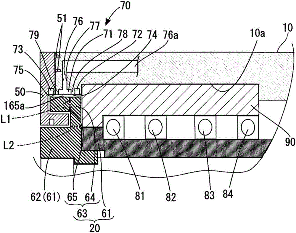
[0021] The housing 10 is formed in a hollow cylindrical shape through which the main shaft 20 can be inserted. The motor 30 is disposed in the cylinder of the housing 10 and includes a stator 31 fixed to the housing 10 and a rotor 32 fixed to the main shaft 20 . The support device 40 rotatably supports the main shaft 20 with respect to the casing 10 . The support device 40 includes a hydrostatic bearing 70 (correspond...


PUM


Abstract

A main shaft device is provided. The main shaft device is provided with a shell (10), a main shaft (20) provided with a main body part (61) holding the cylinder shape of a rotating tool (21) and a flange part (63) protruding from the periphery of the rotating tool (21) of the main body part (61) towards the radical outside, bearings (81-85) bearing the periphery of the main body part (61) to be rotatable relative to the shell (10), and a viscoelastic bearing (hydrostatic bearing (70)) supporting the flange part (63) to allow the flange part to be rotatable relative to the shell (10), arranged at the radical positions of the bearings (81-85) or outside the radical positions and having an attenuation coefficient greater than the attenuation coefficients of the bearings (81-85).

Description

technical field [0001] The present invention relates to spindle devices. Background technique [0002] For example, Japanese Patent No. 5505067 discloses a spindle device that suppresses high-frequency vibration of the spindle during machining by supporting the radial direction of the spindle with a rolling bearing disposed on the tool side of the spindle and a hydrostatic bearing with damping properties. [0003] Since the hydrostatic bearing is arranged near the main shaft, the shear heat of the fluid from the hydrostatic bearing may be transferred to the main shaft to cause a large thermal displacement in the main shaft. In addition, there is a possibility that the recovery space of the fluid of the hydrostatic bearing becomes small, and the reliability of the rotation of the main shaft cannot be ensured. Contents of the invention [0004] One object of the present invention is to provide a spindle device capable of suppressing thermal displacement of the spindle and e...

Claims


Application Information

Patent Timeline
Patent Type & Authority Applications(China)
IPC IPC(8): B23B19/02B23Q11/00
CPCB23Q1/70B23Q11/0003B23Q11/0032
Inventor 松永茂棚濑良太酒井浩一荒井义博田野诚
Owner JTEKT CORP
Why Eureka
Try Eureka