

Conversion lens device and photographing system having the conversion lens device
A lens and optical system technology, applied in the field of shooting systems, can solve problems such as small magnification and inability to use new camera systems
Inactive Publication Date: 2019-08-16
OM DIGITAL SOLUTIONS CORP
View PDF5 Cites 0 Cited by
- Summary
- Abstract
- Description
- Claims
- Application Information
AI Technical Summary
Problems solved by technology
These rear teleconversion lenses are premised on a longer flange backing, so cannot be used with the new camera systems mentioned above
On the other hand, the rear telephoto conversion lens disclosed in Patent Document 3 is a rear telephoto converter suitable for a camera system with a short flange backing, but the magnification is small.
Method used
View moreImage
Smart ImageViewing Examples

Examples
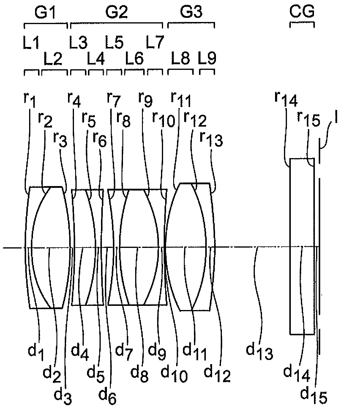
Embodiment 1
[0446] unit mm
[0447] surface data
[0448]
[0449]
[0450] Image surface
[0451] Distance from the main lens = 3.2632
[0452] Various data (unlimited)
[0453]
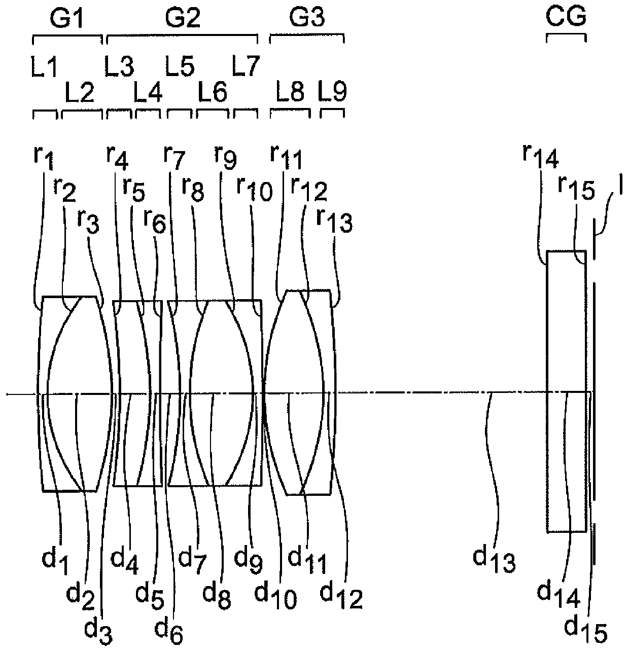
Embodiment 2
[0455] unit mm
[0456] surface data
[0457]
[0458]
[0459] Image surface
[0460] Distance from the main lens = 2.2632
[0461] Various data (unlimited)
[0462]
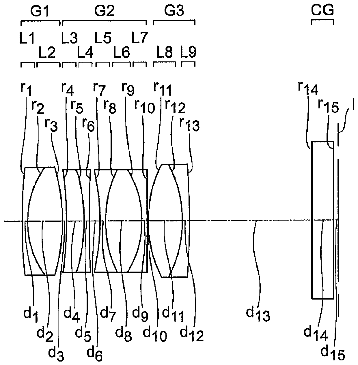
Embodiment 3
[0464] unit mm
[0465] surface data
[0466]
[0467]
[0468] Image surface
[0469] Distance from the main lens = 1.2632
[0470] Various data (unlimited)
[0471]
Login to View More PUM
 Abstract
The present disclosure is directed to a converter lens device that includes a first mount to which a master lens device is capable of being attached, a second mount to which a camera body is capable of being attached and a converter lens having a negative refractive power, wherein, an optical system comprising the converter lens device and the master lens device has a focal length longer than a focal length of an optical system of the master lens device, the converter lens comprises sequentially from an object side, a first lens unit of a positive refractive power, a second lens unit of a negative refractive power, and a third lens unit.
Description
technical field [0001] The present invention relates to a conversion lens device for obtaining an optical system having a focal length longer than that of an optical system of a main lens device and an imaging system having the conversion lens device. Background technique [0002] Conventionally, a conversion lens is known as an optical system for changing the focal length of a main lens. The conversion lens is mounted on the object side of the main lens or the image side of the main lens when used. A conversion lens mounted on the image side of the main lens is called a rear conversion lens. [0003] Two mounting parts are provided in the conversion lens device having the rear conversion lens. One mount portion is a mount portion corresponding to the mount portion of the main lens device, and the other mount portion is a mount portion corresponding to the mount portion of the camera body. [0004] When the conversion lens unit is used, the conversion lens unit is sandwic...
Claims
Login to View More Application Information
Patent Timeline
 Patent Type & AuthorityPatents(China)
IPC IPC(8): G02B13/00G02B15/12
Inventor小方康司
OwnerOM DIGITAL SOLUTIONS CORP