Totality control system

A total amount and controller technology, applied in the field of total amount control system, can solve the problems of rising working temperature, loss cost, power waste, etc.

Inactive Publication Date: 2016-10-05
LIGHTSTAR INFORMATION
View PDF7 Cites 0 Cited by
  • Summary
  • Abstract
  • Description
  • Claims
  • Application Information

AI Technical Summary

Problems solved by technology

[0007] Although the above-mentioned prior art solves the problem that the operating temperature of the chip and other parts in the driver keeps rising, and avoids the problem that the circuit short circuit causes the load to burn out, these technical means still have the problem that the lamp is always at full load current, resulting in unnecessary power waste and loss. cost

Method used


Image

  • Totality control system
  • Totality control system
  • Totality control system

Examples


Embodiment Construction

[0034] In order to make the structural features of the present invention and the achieved effects have a further understanding and recognition, preferred embodiments and detailed descriptions are specially used, which are described as follows:

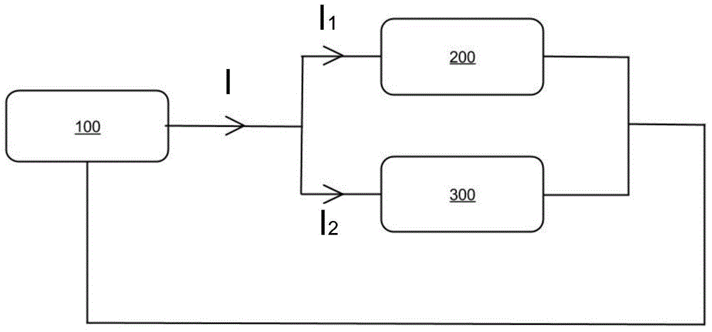
[0035] refer to image 3 , which is a block diagram of a total amount control system in a preferred embodiment of the present invention; as shown in the figure, a total amount control system of the present invention includes: a DC power supply 100, a first electrical device 200 and a second electrical device 300 .

[0036] The DC power supply 100 provides a constant current I, and the DC power supply 100 is an AC power input and a DC power output; a first electrical device 200 is coupled to the DC power supply 100, and the DC power supply Provide a first operating current I 1 , the first electrical device 200 has a first maximum current limit I 1max , if the current flowing through the first electrical device 200 exceeds the first m...


PUM


Abstract

The present invention provides a totality control system comprising a DC power supply as a constant DC current supplier that provides a first working current to a first electric device and a second working current to a second electric device, and a first current limitation and a second current limitation. The current limit will be less than or equal to maximum currents of the electric devices, thereby achieving the power-saving effect by controlling the adjustment of currents.

Description

technical field [0001] The invention relates to a control system, which relates to a total control system which uses constant current output to control the energy consumption of electrical devices. Background technique [0002] In today's era of high awareness of environmental protection, the development and consumption of energy has been paid more attention. In terms of energy consumption, saving electricity is the main consideration, because the traditional electric energy production process consumes a lot of environmental resources, and the use of electric energy will cause environmental burdens. In addition, in order to promote social welfare, the governments of various countries often adopt measures to increase electricity prices to increase national finances, and indirectly promote electricity users to independently manage electricity consumption to achieve the effect of environmental protection and energy conservation. Therefore, if the power consumption can be effec...

Claims


Application Information

Patent Timeline
IPC IPC(8): H02J3/10H05B37/02
Inventor 林明毅
Owner LIGHTSTAR INFORMATION
Why Eureka
Try Eureka