Spring rod preassembling structure, stamping cutter head and processing jig

A spring rod, punching knife technology, applied in the direction of manufacturing tools, metal processing equipment, feeding devices, etc., to avoid wasting materials and reduce production costs

Active Publication Date: 2016-10-12
QINGDAO GOERTEK
View PDF7 Cites 0 Cited by
  • Summary
  • Abstract
  • Description
  • Claims
  • Application Information

AI Technical Summary

Problems solved by technology

[0003] The first object of the present invention is to provide a spring rod preloading structure, aiming

Method used


Image

  • Spring rod preassembling structure, stamping cutter head and processing jig
  • Spring rod preassembling structure, stamping cutter head and processing jig
  • Spring rod preassembling structure, stamping cutter head and processing jig

Examples


Embodiment Construction

[0029] In order to make the object, technical solution and advantages of the present invention more clear, the present invention will be further described in detail below in conjunction with the accompanying drawings and embodiments. It should be understood that the specific embodiments described here are only used to explain the present invention, not to limit the present invention.

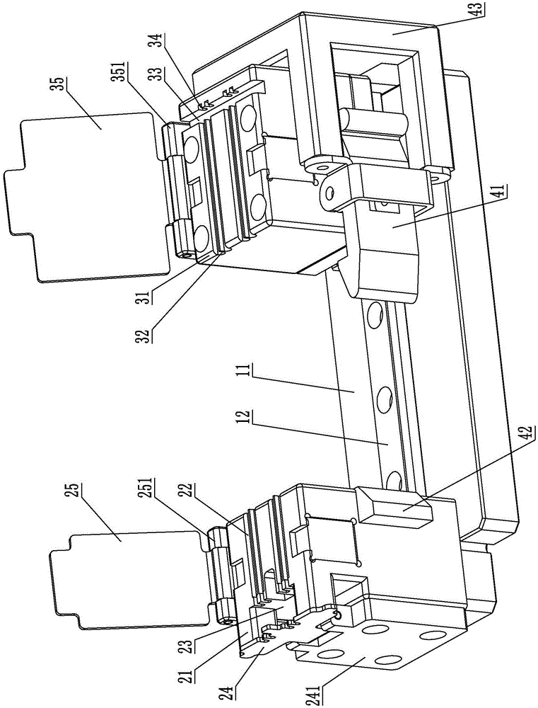
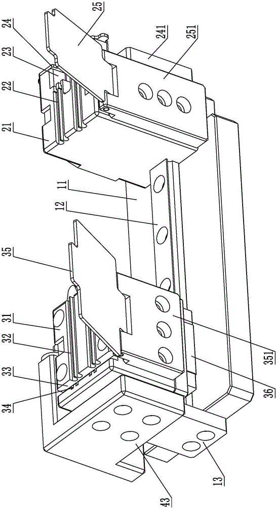
[0030] Depend on figure 1 and figure 2It can be seen that the pre-installed structure of the spring bar includes a pre-installed base plate 11, a linear slide rail 12 installed on the pre-installed base plate 11, a slide rail stopper 13 is provided at one end of the linear slide rail 12, and a slide rail stopper 13 is arranged on the other end of the linear slide rail 12 One end is provided with a front-end positioning seat 21, and a rear-end positioning seat 31 that can slide along the linear slide rail 12 is provided between the slide rail stopper 13 and the front-end positioning seat 21; 1...


PUM


Abstract

The invention belongs to the technical field of spring rod processing equipment, and particularly relates to a spring rod preassembling structure, a stamping cutter head and a processing jig. The spring rod pre-mounting structure comprises a preassembling baseplate and a linear slide rail, wherein a slide rail stopping block is arranged at one end of the linear slide rail, a front end positioning seat is arranged at the other end of the linear slide rail, and a back end positioning seat is arranged between the slide rail stopping block and the front end positioning seat; front placing grooves are formed in the front end positioning seat, a front spring cover plate is rotationally arranged on one side of the front end positioning seat, a cavity is arranged on the other side, away from the back end positioning seat, of the front spring cover plate, stopping parts are arranged on the groove walls of the front placing grooves and near the cavity, and a stopping block cover plate is rotationally arranged on one side of the cavity; back placing grooves are formed in the back end positioning seat, an accommodating groove communicated with the back placing grooves is also formed in the back end positioning seat, bearing grooves are correspondingly formed in the side wall of the accommodating groove, and a back end spring cover plate is rotationally arranged at the side part of the back end positioning seat; a magnet is arranged on each of the front end positioning seat and the back end positioning seat, and a connecting structure is also arranged between the front end positioning seat and the back end positioning seat. The problem that the conventional spring preassembling structure can only realize one-end stamping is solved.

Description

technical field [0001] The invention belongs to the technical field of spring rod processing equipment, and in particular relates to a spring rod pre-installation structure, a stamping cutter head and a processing jig. Background technique [0002] As an indispensable part of the manufacturing industry, the spring rod includes a hollow tube and a spring sleeved on the hollow tube in a compressed state. A stamped blocking protrusion is respectively provided at both ends of the hollow tube to make the spring In the compressed state, the spring rod is widely used in the electronics and electrical appliance manufacturing industries. At present, the traditional spring rod stamping can only complete the stamping of one end of the hollow tube. At present, many industries need to pre-install the spring into the spring rod to compress the spring and then press the second time, so that the spring is stuck and the spring rod is not punched. After the secondary stamping is completed, i...

Claims


Application Information

Patent Timeline
IPC IPC(8): B21D19/08B21D43/00
CPCB21D19/08B21D43/003
Inventor 许文彬
Owner QINGDAO GOERTEK
Why Eureka
Try Eureka