
Implementation method of multi-core timer and multi-core system

An implementation method and multi-core system technology, applied in the field of multi-core timer implementation and multi-core system, can solve problems such as low timer efficiency and uneven multi-core load, so as to avoid information loss and delay, improve timing efficiency and system stability, Solve the effect of overloading

Inactive Publication Date: 2019-03-05
COMBA TELECOM SYST CHINA LTD
View PDF6 Cites 0 Cited by
  • Summary
  • Abstract
  • Description
  • Claims
  • Application Information

AI Technical Summary

Problems solved by technology

[0007] Based on this, it is necessary to provide a method for implementing a multi-core timer and a multi-core system for the problems of uneven multi-core load, low timer efficiency, and system stability in the implementation of a multi-core timer.

Method used


Image

  • Implementation method of multi-core timer and multi-core system
  • Implementation method of multi-core timer and multi-core system
  • Implementation method of multi-core timer and multi-core system

Examples


Embodiment 1

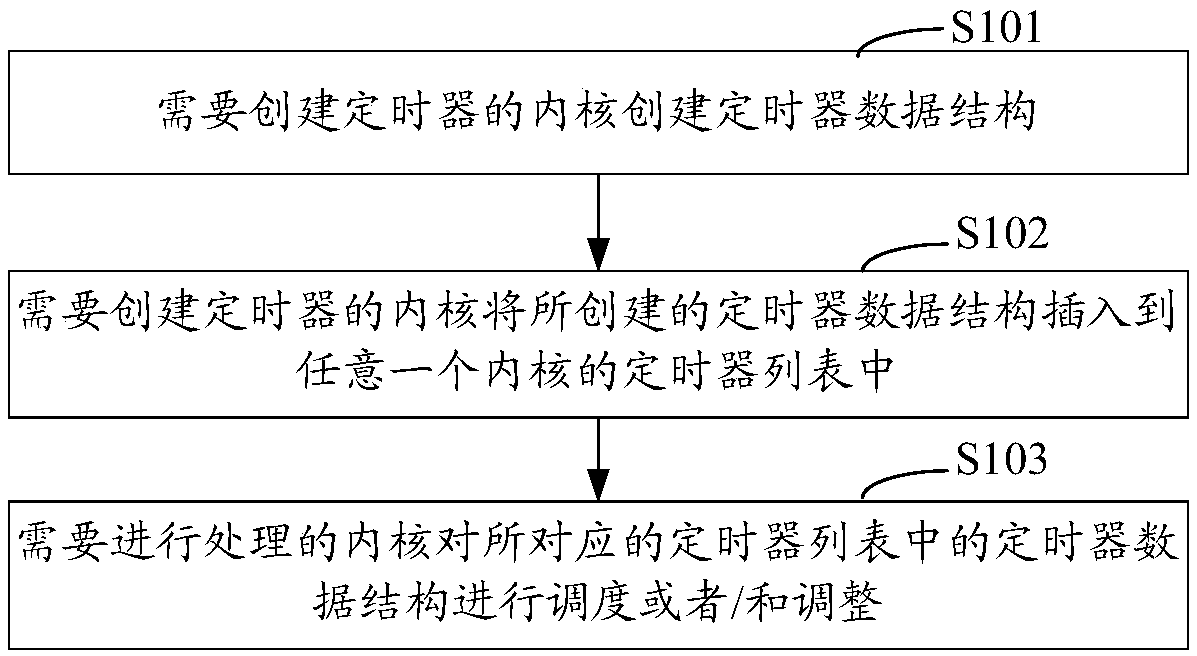
[0028] Embodiment 1 of the present invention provides a method for implementing a multi-core timer, figure 1 It is a schematic diagram of the implementation process of the multi-core timer implementation method in Embodiment 1 of the present invention Figure 1 , in this embodiment, a timer list with the same number of cores as the multi-core system is pre-configured, wherein each core corresponds to one timer list, such as figure 1 As shown, the multi-core timer implementation method in this embodiment includes:

[0029] Step S101: the kernel that needs to create a timer creates a timer data structure;

[0030] Here, the need to create a timer is any core in the multi-core system that currently needs to create a timer;

[0031] Here, the timer data structure is a storage structure of timer data (or called timer related information), which is used to save timer related information;

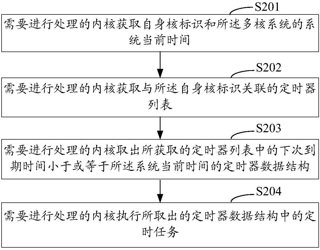
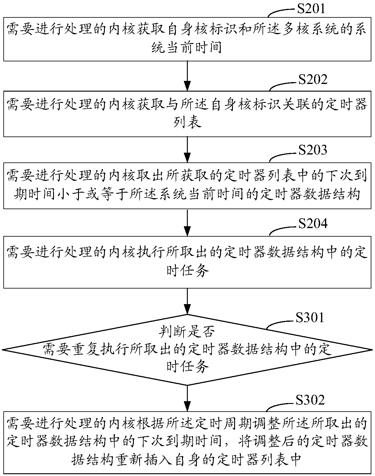
[0032] Step S102: The kernel that needs to create a timer inserts the created timer data st...

Embodiment 2

[0073] Based on the first embodiment above, the second embodiment of the present invention provides a multi-core system, see Figure 5 As shown, it is a schematic diagram of the composition and structure of the multi-core system in Embodiment 2 of the present invention Figure 1 ;like Figure 5 As shown, the multi-core system in this embodiment includes multiple cores 50, and each core 50 in the multiple cores 50 is respectively configured with a timer list, and each core 50 in the multiple cores 50 includes:

[0074] A creation unit 501, configured to create a timer data structure;

[0075] Insertion unit 502, for inserting the timer data structure created by creation unit 501 into the timer list of any kernel;

[0076] The processing unit 503 is configured to process the timer data structure in the corresponding timer list.

[0077] In one of the embodiments, the timer data structure is used to save timer-related information, and the timer-related information includes the...


PUM


Abstract

The present invention relates to a multi-core timer implementation method and a multi-core system. The multi-core timer implementation method is characterized in that timer lists having the same number as cores of the multi-core system are configured in advance, wherein each core is corresponding to one timer list. The method comprises that the core required to create a timer creates a timer data structure; the core required to create a timer inserts the created timer data structure into a timer list of any one core; and the core required to be processed schedules or / and adjusts the timer data structure in the corresponding timer list. By adoption of the scheme, management of timer tasks and execution of timing tasks can be shared by each core, and the problem that load is heavy due to centralized management is solved; and interaction between cores are prevented, information loss and delay are avoided, and timing efficiency and system stability are improved.

Description

technical field [0001] The invention relates to the field of computer multi-core technology, in particular to a method for realizing a multi-core timer and a multi-core system. Background technique [0002] With the advent of the era of big data, the communication system requires more and more processing power for network equipment, and only relying on increasing the speed of a single-core chip to improve the processing power of the CPU (Central Processing Unit, central processing unit) will produce excessive Too much heat and no corresponding performance improvement, and its cost performance is also unacceptable. On the other hand, today's systems require multitasking. In this case, multi-core CPU non-coagulation is a good choice. Its advantages are mainly in two aspects: it brings users more powerful computing performance; more importantly, it can satisfy users for multi-tasking and multi-tasking Computing environment requirements. [0003] Since the timer mechanism pro...

Claims


Application Information

Patent Timeline
Patent Type & Authority Patents(China)
IPC IPC(8): G06F1/10
CPCG06F1/10
Inventor 赵剑川
Owner COMBA TELECOM SYST CHINA LTD
Learn More