
Antenna selection in lte/lte-a networks with unlicensed spectrum

A sensor signal and wireless sensor technology, applied in the field of synchronization systems, can solve the problems of inapplicable sports posture analysis and measurement environment, large amount of data calculation, etc., and achieve the effects of prolonging life, precise time synchronization, and eliminating time errors.

Inactive Publication Date: 2016-10-12
(株)阿尔迪泰
View PDF2 Cites 2 Cited by
  • Summary
  • Abstract
  • Description
  • Claims
  • Application Information

AI Technical Summary

Problems solved by technology

However, the prior art has a problem in that it calculates an error caused by transmission delay time etc. due to wireless transmission of sensor signals, and must be accompanied by a process of correcting time information based on the calculated error, due to the above relationship However, the amount of data calculation for synchronization is too much, and in order to calculate the error, it is necessary to use a wired network such as a cable to repeatedly transmit the reference time information to the wireless sensor side. Due to the above inherent relationship, it cannot be applied to sports. Actual measurement environment such as posture analysis

Method used


Image

  • Antenna selection in lte/lte-a networks with unlicensed spectrum
  • Antenna selection in lte/lte-a networks with unlicensed spectrum
  • Antenna selection in lte/lte-a networks with unlicensed spectrum

Examples


Embodiment Construction

[0027] The examples set forth in this specification should not be interpreted or utilized as limiting the scope of the invention. It is a matter of course that the description, including the embodiments of the present specification, has various applications to those of ordinary skill in the art. Therefore, unless limited by the patent claims, any embodiments are illustrated for better illustration of the present invention, and the scope of the present invention is not intended to be limited to the embodiments. In addition, in describing the present invention, when it is judged that a specific description of related well-known configurations or functions may obscure the gist of the present invention, the detailed description thereof will be omitted.

[0028] Further, although descriptions of “sending”, “receiving”, “delivering” or “applying” from certain constituent elements to other constituent elements may also directly affect the other constituent elements, it should be unde...


PUM


Abstract

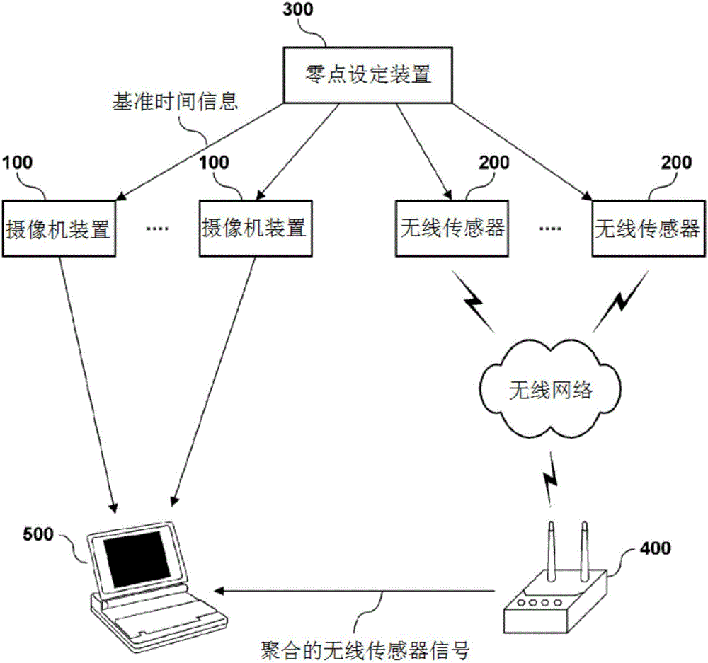
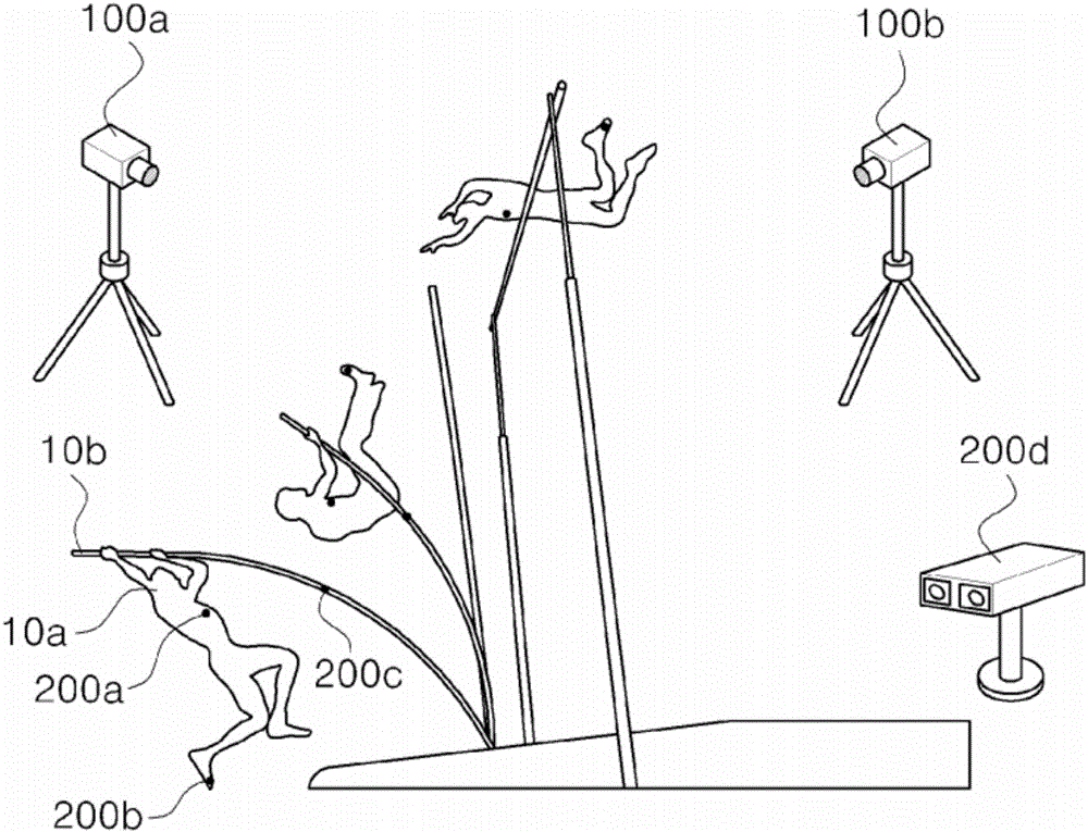
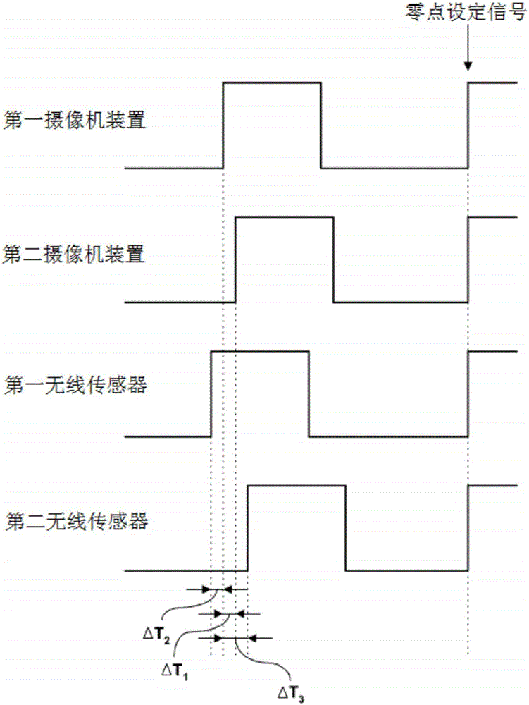
The present invention relates to a system and a method for synchronizing a video signal and a wireless sensor signal. One embodiment of the present invention provides a system for synchronizing a video signal and a wireless sensor signal, the system comprising: a camera device which is provided with a first synchronization clock, generates a video signal by photographing an object, and transmits, to a computing device side, the video signal into which a first time tag is inserted by the first synchronization clock at every first unit time; a wireless sensor which is provided with a second synchronization clock and a wireless communication module, generates a sensor signal by sensing a changing state value from the object or from outside, and transmits, to a sensor signal collecting unit side via the wireless communication module, the video signal into which a second time tag is inserted by the second synchronization clock at every second unit time; a zero-point setting device for transmitting a zero-point setting signal containing reference time information to the camera device side and the wireless sensor side over a wired network; a sensor signal collecting unit which collects a sensor signal that is wirelessly transmitted from the wireless sensor and transmits the sensor signal to the computing device side; and a computing device which receives the video signal and the sensor signal and performs synchronization between the video signal and the sensor signal, wherein a local time of the first synchronization clock and the second synchronization clock is changed to the reference time according to the zero-setting signal, and the computing device performs synchronization of the video signal and the sensor signal on the basis of time information contained in the first time tag and the second time tag.

Description

technical field [0001] The present invention relates to a system and method for synchronizing multiple signals, and more specifically relates to a system and method for synchronizing sensor signals and image signals transmitted wirelessly. Background technique [0002] Recently, with the rapid development of video and communication technologies, attempts are being made to synchronize video signals obtained by photographing moving subjects with sensor signals. [0003] Specifically, unless a plurality of signals are synchronized, it cannot be confirmed whether an event included in an arbitrary video signal and an event included in a sensor signal are the same event, in other words, whether they are at the same time. Therefore, in order to synthesize various signals that vary according to time to derive useful information, it is necessary to make the time between signals transmitted from a plurality of signal aggregation devices connected to the network (network) accurate with...

Claims


Application Information

Patent Timeline
Patent Type & Authority Applications(China)
IPC IPC(8): H04L7/04
CPCH04N5/222H04N5/0675H04N5/073H04N23/661H04N5/0733A63B2220/80A63B2220/00A63B2220/70
Inventor 崔承焕
Owner (株)阿尔迪泰
Learn More