Low temperature environmental test chamber for optical instruments

A low-temperature environment and optical instrument technology, which is applied in the field of optical instruments, can solve problems such as unfeasibility of economic indicators and failure to meet the requirements of testing, and achieve the effects of low cost, reduced heat exchange intensity, and simple operation

Active Publication Date: 2019-03-29
NORTHWEST INST OF ECO ENVIRONMENT & RESOURCES CAS
View PDF11 Cites 0 Cited by
  • Summary
  • Abstract
  • Description
  • Claims
  • Application Information

AI Technical Summary

Problems solved by technology

For some optical instruments with a large measurement space, if the low temperature test is used to simulate the environment, the traditional ground greenhouse is often unable to meet the test requirements due to the limitation of the site, such as long-distance laser positioning or distance measuring equipment, etc., while the construction of large-scale low temperature laboratories and Its operation is often not feasible in terms of economic indicators

Method used


Image

  • Low temperature environmental test chamber for optical instruments

Examples


Embodiment Construction

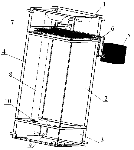
[0015] Such as figure 1 As shown, the low-temperature environment test box for optical instruments, the test box includes a box body 4 made of vacuum double-layer glass and equipped with an upper cavity 1, a middle cavity 2, and a lower cavity 3, and is located on the top of the box 4 and connected to the power supply. connected microcontroller.

[0016] Between the upper cavity 1 and the middle cavity 2, and between the middle cavity 2 and the lower cavity 3, there are partitions, and the partitions are provided with symmetrically distributed ventilation holes 10; the upper cavity 1 passes through the air circulation pipe 8 is directly connected to the lower cavity 3; a fan 7 with a motor is provided on one side of the upper cavity 1; a cooling liquid circulation pipe 6 is provided on the partition where the upper cavity 1 and the middle cavity 2 meet, and the cooling The liquid circulation pipe 6 is externally connected to the refrigerator 5; one side of the lower cavity 3 ...


PUM


Abstract

The invention relates to an optical-instrument low temperature environment test box. The test box comprises that a box body and a single chip microcomputer, wherein the box body is made of vacuum double glazing glass and an internal portion is provided with an upper layer cavity, a middle layer cavity and a lower layer cavity; and the single chip microcomputer is arranged on a top of the box body and is connected to a power supply. Separation plates are arranged between the upper layer cavity and the middle layer cavity, and between the middle layer cavity and the lower layer cavity. The separation plates are provided with vent holes which are symmetrically distributed. The upper layer cavity is directly connected to the lower layer cavity through an air circulating pipe. One side of the upper layer cavity is provided with a fan with a motor. The separation plate located at a connection portion of the upper layer cavity and the middle layer cavity is provided with a cooling fluid circulation pipe. The cooling fluid circulation pipe is externally connected to a refrigerating machine. One side of the lower layer cavity is provided with a temperature sensor. The single chip microcomputer is connected to the fan and the temperature sensor respectively and is externally connected to a keyboard and a liquid crystal display screen. In the invention, cost is low, operation is simple, and a low temperature test environment which is not limited by a space scope can be provided for an optical instrument to be tested.

Description

technical field [0001] The invention relates to the technical field of optical instruments, in particular to a low-temperature environment test box for optical instruments. Background technique [0002] Low temperature detection is a basic test item of the instrument. For some optical instruments with a large measurement space, if the low-temperature test is used to simulate the environment, the traditional ground greenhouse is often unable to meet the test requirements due to the limitation of the site, such as long-distance laser positioning or distance measuring equipment, etc., while the construction of large-scale low-temperature laboratories and Its operation is often not feasible in terms of economic indicators. Therefore, there is an urgent need for a device that requires less investment and can provide a low-temperature test environment for optical instruments. Contents of the invention [0003] The technical problem to be solved by the present invention is to p...

Claims


Application Information

Patent Timeline
Patent Type & Authority Patents(China)
IPC IPC(8): G01M11/00
Inventor 芮鹏飞陈继
Owner NORTHWEST INST OF ECO ENVIRONMENT & RESOURCES CAS
Why Eureka
Try Eureka