Production transmission line for upper shell and lower shell of special-shaped pipe

A special-shaped pipe and transfer line technology, applied in the direction of forming tools, feeding devices, positioning devices, etc., can solve the problems of difficult one-time forming, low efficiency, irregular shape, etc., and achieve precise forming, exquisite workmanship, and setting reasonable effect

Inactive Publication Date: 2016-10-26
WUXI DAWN DIE & STAMPING
View PDF9 Cites 0 Cited by
  • Summary
  • Abstract
  • Description
  • Claims
  • Application Information

AI Technical Summary

Problems solved by technology

[0003] For the above-mentioned special-shaped tubes, due to the various features of their profiles, irregular shapes, and high processing precision requirements, it is difficult to make them by general methods, or it is difficult to form them at one time. Manual transfer in the mold is inefficient

Method used


Image

  • Production transmission line for upper shell and lower shell of special-shaped pipe
  • Production transmission line for upper shell and lower shell of special-shaped pipe
  • Production transmission line for upper shell and lower shell of special-shaped pipe

Examples


Embodiment Construction

[0032] The present invention will be further described below in conjunction with the accompanying drawings.

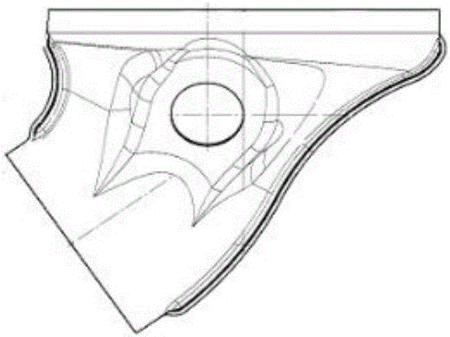
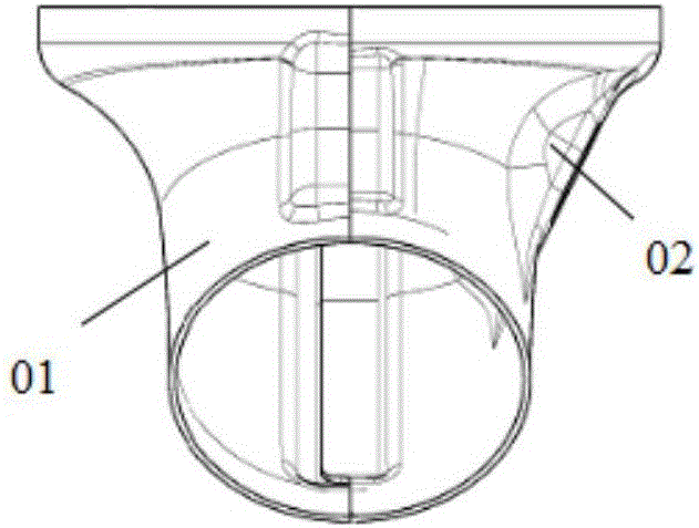
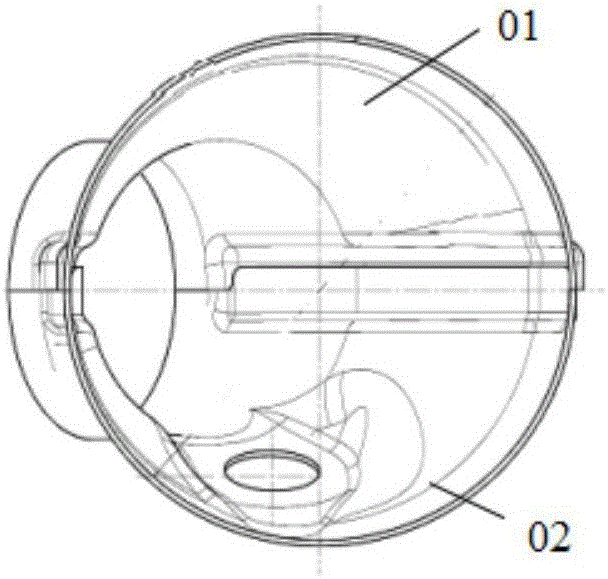
[0033] For attached Figure 1-3 The special-shaped tube shown requires 6 sets of molds to form the finished product, which are as follows from front to back:

[0034] (1) Press out the U-shaped bulge in the middle part of the blank sheet to form the profile of the upper half shell and the lower half shell, and the forming die 22 that connects the big ends of the upper half shell and the lower half shell together. After forming, the workpiece is as attached Figure 4 shown;

[0035] (2) The shaping die 23 for further shaping the workpiece drawn by the forming die 22, after shaping, the workpiece is as attached Figure 5 shown;

[0036] (3) Cut out the small mouth ends of the upper half-shell and the lower half-shell, and cut out the contour line of the middle part of the outer bending edge of the upper half-shell and the middle part of the outer bending edge of the lo...


PUM


Abstract

The invention discloses a production transmission line for an upper shell and a lower shell of a special-shaped pipe. The production transmission line comprises a material accumulating frame used for accumulating blank material pieces, a punching device and a discharging conveying line in sequence from front to back. A workpiece is transmitted among the material accumulating frame, the punching device and the discharging conveying line through a transmission mechanical arm. By means of the production transmission line, the transmission mechanical arm is used for transporting the workpiece from the material accumulating frame to the punching device and conveying the workpiece to make the workpiece pass through multiple special-shaped pipe forming dies installed on a punch in sequence, the operation is stable and fast, and efficiency is extremely high; and in addition, the special-shaped pipe forming dies are arranged reasonably, the technology is exquisite, and accurate forming of the workpiece is facilitated.

Description

technical field [0001] The invention relates to the field of mold-opening part production lines, in particular to a production transfer line for special-shaped pipes. Background technique [0002] The present invention is aimed at the upper half-shell 01 and the lower half-shell 02 of special-shaped tubes of specific shapes, and the structure of the special-shaped tubes is as attached Figure 1-3 As shown, the overall structure of the special-shaped pipe is similar to the elbow joint of the water pipe, but its profile is irregular, and the ports at both ends are large and small, which are called the large end and the small end respectively. The special-shaped pipe is composed of an upper half shell 01 and a lower half shell 02, and the joints of the upper half shell 01 and the lower half-shell 02 are provided with laps, and the laps are respectively located in the inner and outer bends of the special-shaped pipe. There is a boss on the profile surface of the lower half shell...

Claims


Application Information

Patent Timeline
Patent Type & Authority Applications(China)
IPC IPC(8): B21D35/00B21D37/08B21D43/02B21D43/10
CPCB21D35/002B21D37/08B21D43/027B21D43/105
Inventor 白瑛曹一枢段玉霞马远征
Owner WUXI DAWN DIE & STAMPING
Why Eureka
Try Eureka