A clamping device for range hood oil cup

A clamping device and fume-absorbing technology, applied in applications, household appliances, household components, etc., can solve the problems of low plate fixing accuracy, high labor intensity, poor fixing effect, etc., to achieve precise forming, easy maintenance, The effect of reducing the burden

Active Publication Date: 2021-06-15
李梓祥
View PDF7 Cites 0 Cited by
  • Summary
  • Abstract
  • Description
  • Claims
  • Application Information

AI Technical Summary

Problems solved by technology

[0005] In order to overcome the existing problems that the staff hold the cut plates and use mechanical equipment to turn them into shape, which is not only labor-intensive, time-consuming and labor-intensive, but also has low fixing accuracy, poor fixing effect and high risk for the cut plates. Therefore, the technical problem of the present invention is to provide a clamping device for the range hood oil cup that can reduce the burden on the staff and fix the cut plate with high precision

Method used


Image

  • A clamping device for range hood oil cup
  • A clamping device for range hood oil cup
  • A clamping device for range hood oil cup

Examples


Embodiment approach 1

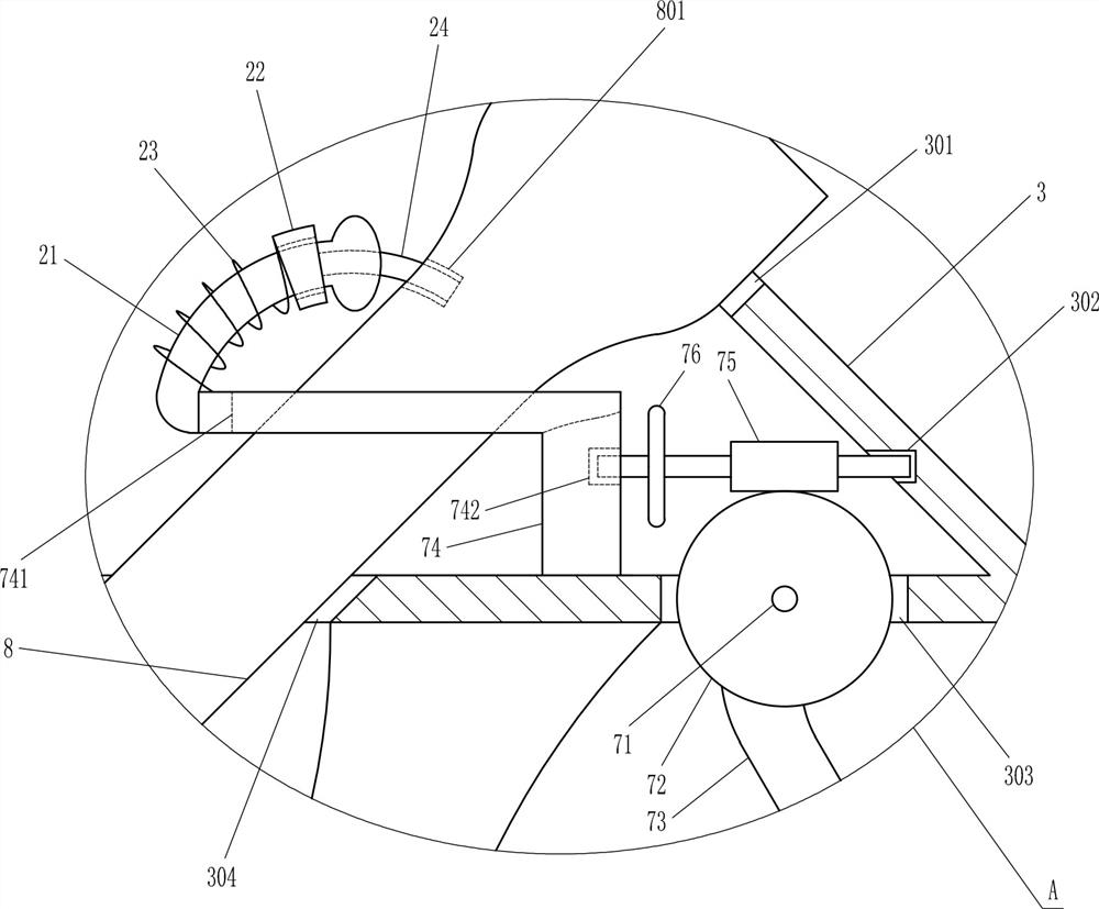
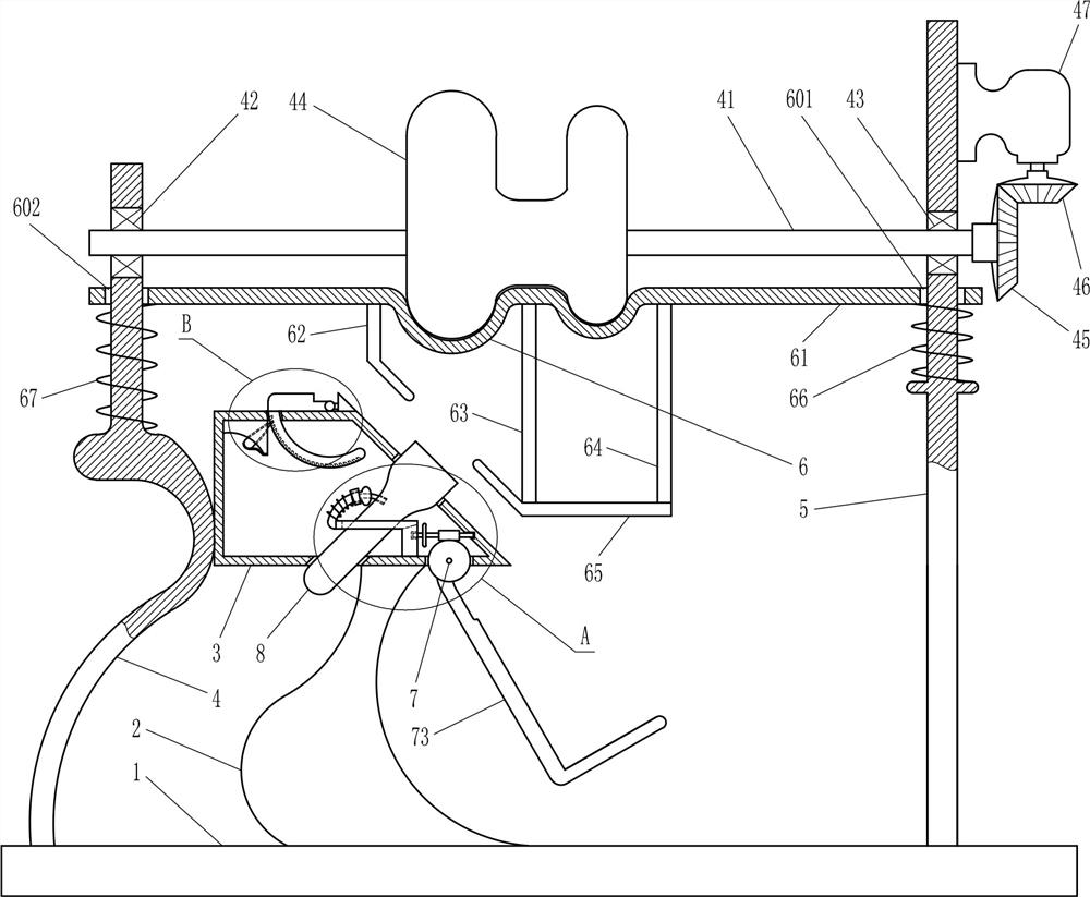
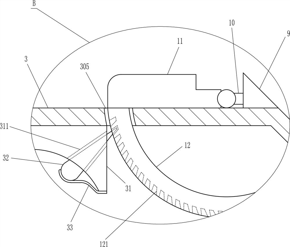
[0019] Please see Figure 1-3, the application is a clamping device for range hood oil cup, including a base 1, a large bracket 2, a wedge-shaped frame 3, a left bracket 4, a right bracket 5, a pressing device 6, a bending device 7, a large The positioning column 8, the triangular block 9, the hinge block 10, the swing plate 11 and the arc guide plate 12, the bottom end of the large bracket 2 is connected with the upper surface of the base 1 by welding, and the outer bottom surface of the wedge frame 3 is connected by welding The way is connected with the top of the large bracket 2, the right slope of the wedge frame 3 has a large round hole 301 inclined, the inner right slope of the wedge frame 3 has a horizontal first blind hole 302, the first blind hole 302 Be arranged below the large round hole 301, the bottom surface of the wedge frame 3 is vertically provided with a movable groove 303, the movable groove 303 is arranged on the right side of the top of the large bracket 2...

Embodiment approach 2

[0022] Please see Figure 1-3 , on the basis of Embodiment 1, the pressing device 6 includes a large lifting plate 61, a large pressing plate 62, a first connecting plate 63, a second connecting plate 64, a long pressing plate 65, a first spring 66 and a second spring 67, the large lifting plate 61 is arranged on the top of the triangular block 9, the hinged block 10 and the swing plate 11, the right end of the large lifting plate 61 has a first lifting hole 601, and the top of the right bracket 5 is located in the first lifting hole 601. The left end of lifting plate 61 has second lifting hole 602, and the top of left support 4 is positioned at second lifting hole 602, and the upper end of big pressing plate 62, the upper end of first connecting plate 63 and the upper end of second connecting plate 64 are all connected with The bottom surface of the big lifting plate 61 is connected by welding, the big pressing plate 62, the first connecting plate 63 and the second connecting...

Embodiment approach 3

[0025] Please see Figure 1-3 , on the basis of Embodiment 1 and Embodiment 2, the bending device 7 includes a rotating shaft 71, a worm wheel 72, an L-shaped pressing plate 73, an L-shaped fixing plate 74, a worm screw 75 and a rotating disk 76, and the rotating shaft 71 is located at In the movable groove 303, the front end and the rear end of the rotating shaft 71 are connected to the wedge frame 3 by welding, the center position of the worm wheel 72 is rotatably sleeved on the rotating shaft 71, and the left upper end of the L-shaped extrusion plate 73 is connected to the worm wheel. The lower side of 72 is connected by welding, the lower right end of the L-shaped fixed plate 74 is connected with the inner bottom surface of the wedge frame 3 by welding, and the lower right end of the L-shaped fixed plate 74 is arranged between the movable groove 303 and the inclined hole 304 Between, the upper left part of the L-shaped fixed plate 74 has a lift groove 741, the large positi...


PUM


Abstract

The invention relates to a clamping device, in particular to a clamping device for an oil cup of a range hood. Therefore, the technical problem of the present invention is how to provide a clamping device for the oil cup of the range hood that can reduce the burden on the staff and fix the cut plate with high precision. The clamping device for the range hood oil cup includes a base, a large bracket, a wedge-shaped frame, a left bracket, a right bracket, etc.; the upper surface of the base is fixed with a large bracket, and the top of the large bracket is fixed with a wedge-shaped frame. The left side of the frame is fixedly connected with a left bracket, the lower end of the left bracket is fixedly connected with the upper surface of the base, the upper surface of the base is fixedly connected with a right bracket, and the right bracket is arranged on the right side of the wedge-shaped frame. The invention can precisely position the cut plate through the large positioning column, so as to precisely fix it, has good fixing effect, and is beneficial to precise forming.

Description

technical field [0001] The invention relates to a clamping device, in particular to a clamping device for an oil cup of a range hood. Background technique [0002] There is an oil cup at the bottom of the range hood. During the use of the range hood, the range hood exhausts the smoke and filters the oil in the range hood. After the temperature cools down, the oil droplets will flow down and deposit in the Temporary storage in the oil cup. In the production process of the oil cup, the plate is usually cut first, then folded into shape, and then welded and fixed. [0003] At present, the staff hold the cut boards and use mechanical equipment to fold them into shape, which is not only labor-intensive, time-consuming and labor-intensive, but also fixes the cut boards with low accuracy, poor fixing effect, and high risk. Patent application 201810498179.6 discloses a clamp for welding, including: a frame, a worktable is arranged on the top of the frame; a side clamp assembly is p...

Claims


Application Information

Patent Timeline
Patent Type & Authority Patents(China)
IPC IPC(8): B29C53/04B29C53/80B29L31/00
CPCB29C53/04B29C53/80B29L2031/712
Inventor 尹艳红
Owner 李梓祥
Why Eureka
Try Eureka