
Rapid fixing frame for crankshaft submerged arc welding

A submerged arc welding and fixing frame technology, which is applied in arc welding equipment, welding equipment, welding accessories, etc., can solve problems such as submerged arc welding difficulties, and achieve the effect of improving the convenience and accuracy of positioning

Active Publication Date: 2016-10-26
ANHUI REMFG ENG DESIGN CENT
View PDF8 Cites 5 Cited by
  • Summary
  • Abstract
  • Description
  • Claims
  • Application Information

AI Technical Summary

Problems solved by technology

[0003] Large crankshafts are not uncommon in special fields such as industrial mining and energy. After the working surface of large crankshafts is worn out, submerged arc welding is required. The centers of rotation of the two do not coincide, thus causing great difficulties for submerged arc welding

Method used


Image

  • Rapid fixing frame for crankshaft submerged arc welding
  • Rapid fixing frame for crankshaft submerged arc welding

Examples


Embodiment Construction

[0017] In order to make the technical means, creative features, goals and effects achieved by the present invention easy to understand, the present invention will be further elaborated below.

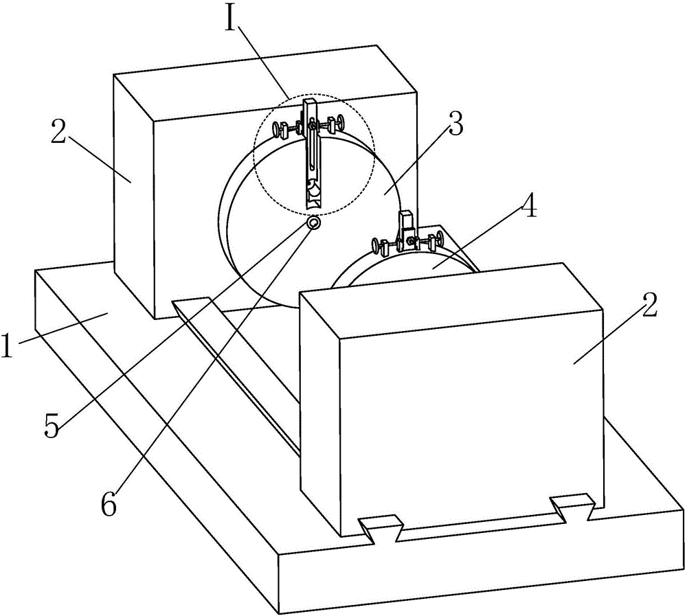
[0018] Such as figure 1 , figure 2 As shown, a fast fixing frame for crankshaft submerged arc welding includes a welding platform 1, a lathe 2 is respectively provided on the left and right sides of the welding platform 1, the right part of the left lathe 2 and the right lathe 2 The left part is correspondingly equipped with a left track chuck 3 and a right single track chuck 4 respectively.

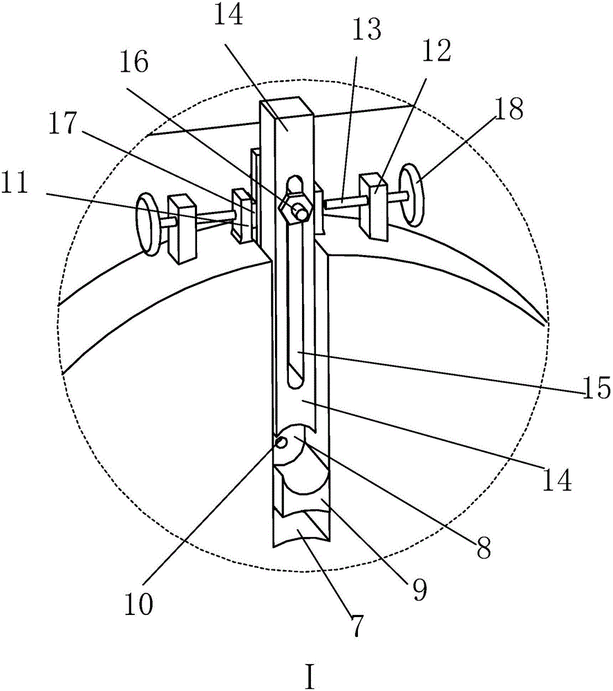
[0019] The middle part of the right end face of the left rail chuck 3 is provided with a circular groove 5, and a No. 1 laser light 6 is fixedly installed in the circular groove 5, and the beam of the No. 1 laser lamp 6 coincides with the axis of the left rail chuck 3; The upper part of the left end surface of the left rail chuck 3 is provided with a left middle groove 7 , and the upper part of...


PUM


Abstract

The invention relates to a rapid fixing frame for crankshaft submerged arc welding. The rapid fixing frame comprises a welding table, the left side and the right side of the welding table are each provided with a lathe, the right portion of the left lathe is correspondingly provided with a left rail chuck, the left portion of the right lathe is correspondingly provided with a right single-rail chuck, a round groove is formed in the middle of the right end face of the left rail chuck, a first laser lamp is fixedly mounted in the round groove, a light column of the first laser lamp coincides with the axis of the left rail chuck, a left middle groove is formed in the upper portion of the left end face of the left rail chuck, and the upper portion of the left middle groove extends to the circumference face of the left rail chuck; and the function that the left rail chuck and the right single-rail chuck carry out radial adjustment along the corresponding chucks is utilized for carrying out eccentric clamping on a crankshaft, a rotating shaft of the crankshaft is located on the side portions of the left rail chuck and the right single-rail chuck, and therefore the axis of a to-be-welded work shaft of the crankshaft is moved to the position where the axis of the left rail chuck and the axis of the right single-rail chuck coincide, and therefore the aim that the crankshaft rotates around the axis of the working shaft of the crankshaft is achieved.

Description

technical field [0001] The invention relates to the technical field of heat treatment fixing equipment for shaft parts, in particular to a fast fixing frame for crankshaft submerged arc welding. Background technique [0002] With the expansion of the field of people's activities, various large-scale equipment is widely used. Large-scale equipment wears a lot and is difficult to repair by traditional repair techniques. Submerged arc welding is widely used as an effective technical means for large-scale wear repair. [0003] Large crankshafts are not uncommon in special fields such as industrial mining and energy. After the working surface of large crankshafts is worn out, submerged arc welding is required. The rotation centers of the two do not coincide, so it causes great difficulties for submerged arc welding. Contents of the invention [0004] In view of the above defects, the present invention proposes a fast fixing frame for crankshaft submerged arc welding. [0005]...

Claims


Application Information

Patent Timeline
Patent Type & Authority Applications(China)
IPC IPC(8): B23K9/18B23K9/32
CPCB23K9/18B23K9/32
Inventor 程敬卿周乾坤
Owner ANHUI REMFG ENG DESIGN CENT
Learn More