Check patentability & draft patents in minutes with Patsnap Eureka AI!

Robotic system with reconfigurable end effector assembly

A technology of robot system and manipulator, applied in the field of robot system

Active Publication Date: 2018-08-31
GM GLOBAL TECH OPERATIONS LLC +1
View PDF7 Cites 0 Cited by
  • Summary
  • Abstract
  • Description
  • Claims
  • Application Information

AI Technical Summary

Problems solved by technology

Together, the robot, end effector assembly, and configuration tool address some of the above-mentioned problems associated with existing end effector designs.

Method used


Image

  • Robotic system with reconfigurable end effector assembly
  • Robotic system with reconfigurable end effector assembly
  • Robotic system with reconfigurable end effector assembly

Examples


Embodiment Construction

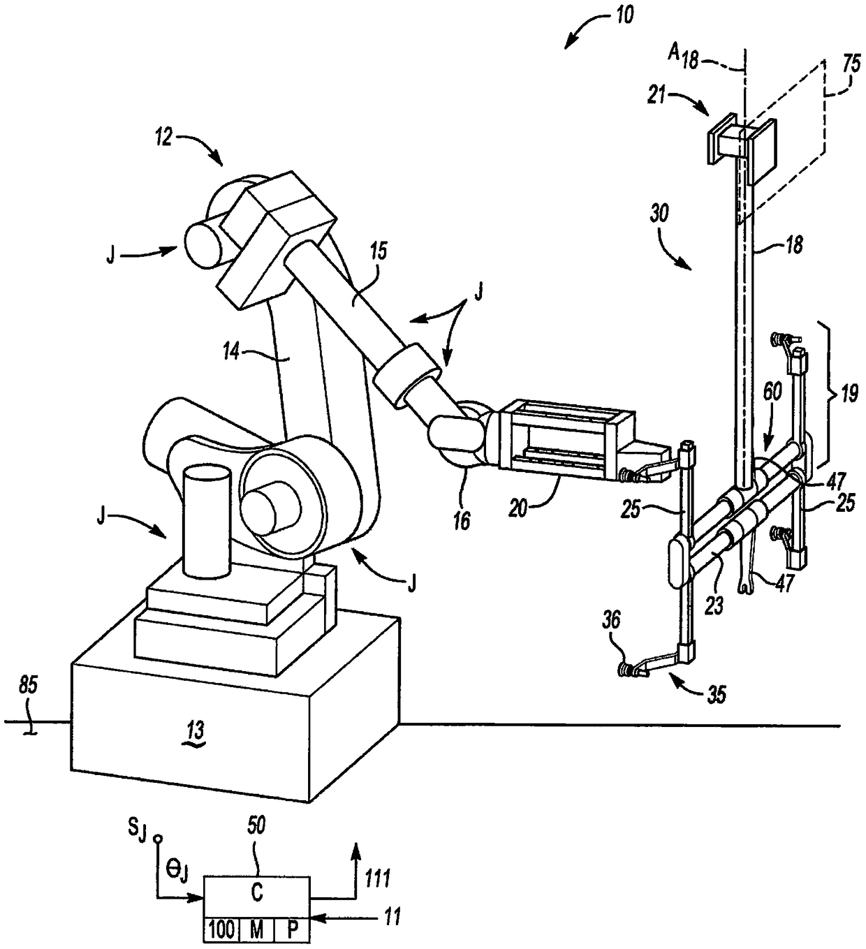
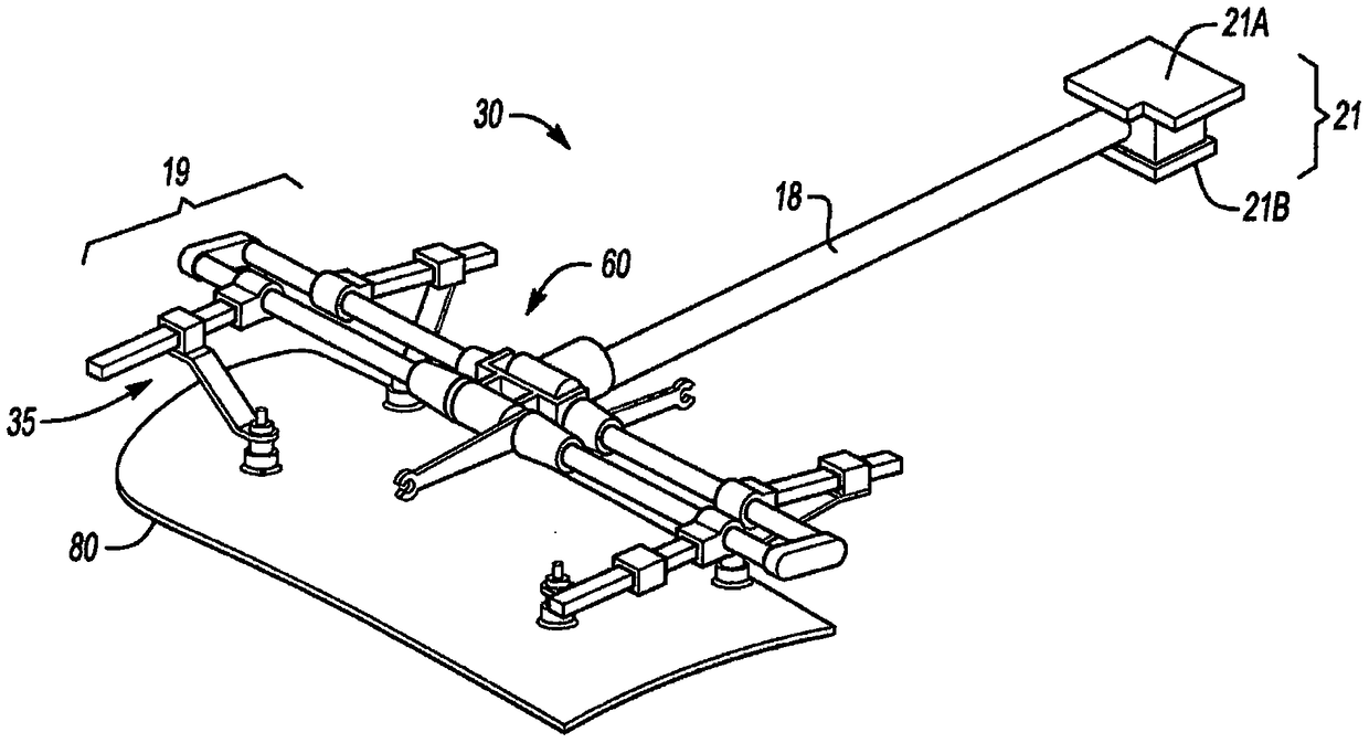
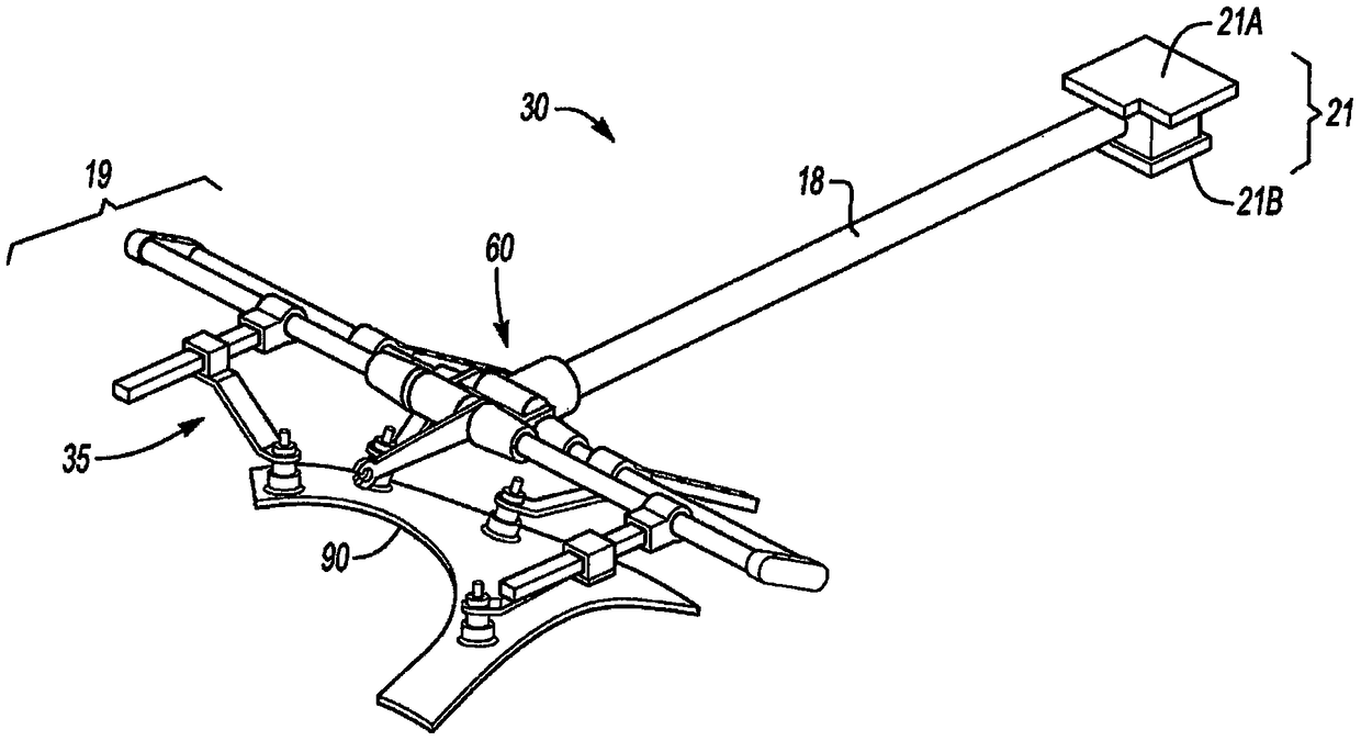
[0053] Referring to the drawings, wherein like reference numerals designate like parts throughout the several views, in figure 1 The robotic system 10 is schematically shown in . The robot system 10 includes a multi-axis industrial robot 12, Figure 5 and 6 The configuration tool 20 best shown in , and referenced below Figure 2A-4 and 7 describe the reconfigurable end effector assembly 30 in detail. Overall operational control of the robotic system 10 may be achieved by the controller (C) 50 via execution of the method 100, an example implementation of which is at Figure 8 shown in . Robotic system 10 may be included in Figure 9-11E The configuration rack 75, 175 described in detail in, the method 200 of using the configuration rack 75, 175 in Figure 12 shown in .

[0054] figure 1 The robot 12 may be implemented as a conventional 6-axis industrial robot as shown, and thus may include a fixed or moving base 13 and a plurality of robot joints J, at least some of whi...


PUM


Abstract

The robotic system includes a robot, an end effector assembly disposed at the end of a main arm, a rotatable parallel frame crossbar, and a tool support branch. The tool assemblies are connected to the tool support branches and are rotatable / movable relative to the respective branch axes. The configuration tool has control blocks and tools that are engaged by the robot's wrist. The controller directs the robot to automatically configure the end effector assembly using the tool by adjusting the frame crossbar and / or tool support branches or tool assembly, in response to the identified work task to do so. Direct the engagement of the wrist and tool changer and perform the identified work tasks using the end effector assembly. The deployment rack automatically flips the end effector assembly into the deployment position, directs the engagement of the wrist with the tool changer, and deploys the end effector assembly.

Description

technical field [0001] The present disclosure relates to robotic systems with reconfigurable end effector assemblies. Background technique [0002] Multi-axis industrial robots consist of articulated arms connected by shoulder joints. Each part is driven by one or more joint motors. A typical industrial robot is controlled with respect to six different control axes. Collectively, these control axes enable rotation of the robot relative to a fixed or moving base, extension / retraction of the first arm, and raising / lowering of the second arm as well as rotation of the shoulder joint and the Rotation / translation of the wrist. Additional arms can be used in a serial arrangement depending on the design, while the end effector attached to the wrist can be manipulated to perform the desired work task. [0003] The term "end effector" refers to the specific end linkage or component that, depending on the design of the robot, safely grasps, transfers, orients, and releases a workp...

Claims


Application Information

Patent Timeline
Patent Type & Authority Patents(China)
IPC IPC(8): B25J15/00B25J15/06
CPCB25J15/0052B25J15/0616G05B2219/39468B25J15/0061Y10S901/41B25J9/163
Inventor Y-T·林J·波勒斯K·德拉赫M·珀尔曼
Owner GM GLOBAL TECH OPERATIONS LLC
Features
  • R&D
  • Intellectual Property
  • Life Sciences
  • Materials
  • Tech Scout
  • Unparalleled Data Quality
  • Higher Quality Content
  • 60% Fewer Hallucinations
Learn More