Bumper injection mold deformation space avoiding mechanism

A technology of deforming space and injection mold, which is applied to household appliances, other household appliances, household components, etc., can solve the problems of inability to achieve automatic demoulding, increase labor costs, and reduce production efficiency.

Active Publication Date: 2016-10-26
TAIZHOU HUANGYAN KUNTAI MOLD CO LTD
View PDF7 Cites 3 Cited by
  • Summary
  • Abstract
  • Description
  • Claims
  • Application Information

AI Technical Summary

Problems solved by technology

[0002] After the injection mold injection molds the bumper, if the two ends of the bumper are made with a downward arc surface, and the lower end of the arc surface is made with a lower inner undercut, the front side of the arc surface is made with a side inner undercut, and the lower inner There is an included angle of 90° between the undercut and the side undercut, so the inserts of the lower undercut and the inserts of the side undercut limit the space for inward displacement. Push out the inserts at the lower undercut and side undercut positions together with the bumper, and then take advantage of the elastic characteristics of the bumper material to manually remove the bumper. This will not allow automatic demoulding, which will increase the labor of workers Intensity and increased labor costs, and reduced production efficiency

Method used


Image

  • Bumper injection mold deformation space avoiding mechanism
  • Bumper injection mold deformation space avoiding mechanism
  • Bumper injection mold deformation space avoiding mechanism

Examples


Embodiment Construction

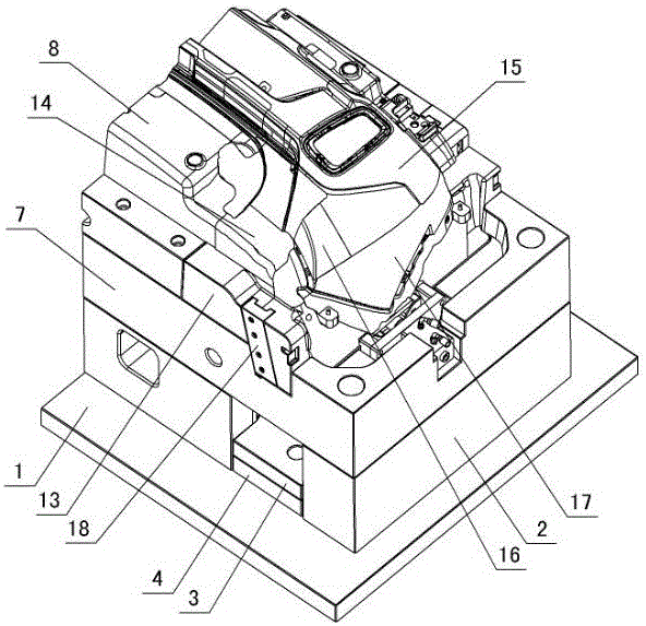
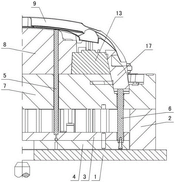
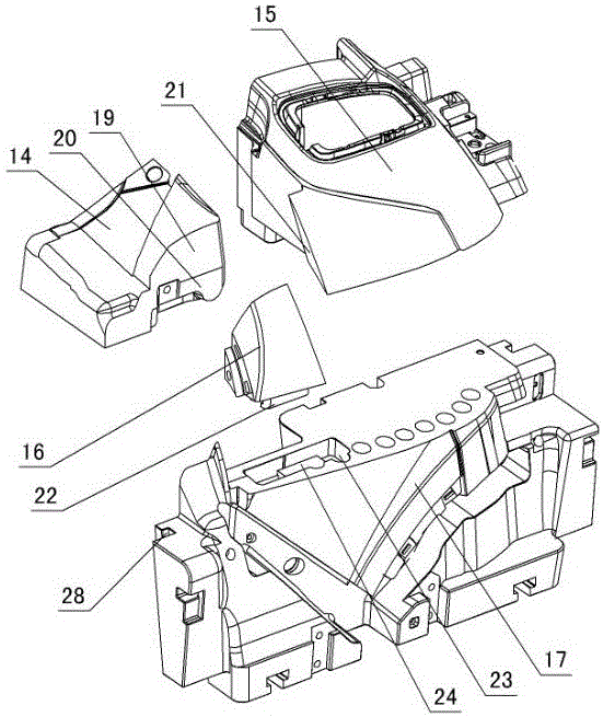
[0012] The invention relates to a bumper injection mold deformation space relief mechanism, such as figure 1 — Figure 5 As shown, it includes the lower doubler plate 1, the mold foot 2 is set on the lower doubler plate, the upper ejector plate 3 and the lower ejector plate 4 are arranged on the lower doubler plate between the mold feet, the upper ejector pin 5 is arranged on the upper ejector plate, and the lower ejector plate The lower thimble 6 is arranged on the top, the movable template 7 is arranged on the mold foot, the movable mold insert 8 is arranged on the movable template, the bumper 9 is injection-molded on the movable mold insert, and the two ends of the bumper are formed with downward curved surfaces 10 , a lower inner undercut 11 is formed under the arc surface, and a side inner undercut 12 is formed on the front side of the arc surface. It is characterized in that: the movable template 7 is provided with a guide rail mounting seat 13 on one side of the movable...


PUM


Abstract

The invention discloses a bumper injection mold deformation space avoiding mechanism. A lower compound plate is provided with a mold foot, an upper ejector plate and a lower ejector plate. The upper ejector plate is provided with an upper ejector. The lower ejector plate is provided with a lower ejector. The mold foot is provided with a movable mold plate provided with a movable mold insert. The movable mold insert is provided with a bumper. Arc faces are manufactured at the two ends of the bumper. Lower inner reverse buckles and side inner reverse buckles are manufactured below the arc faces. The bumper injection mold deformation space avoiding mechanism is characterized in that the part, located on one side of the movable mold insert, of the movable mold plate is provided with a guide rail installing base, a fixing base, a straight ejector block, a side core drawing avoiding block and an inner core drawing sliding block, an inclined guide rail is arranged on one side of the guide rail installing base, and an upper slope and a lower straight face are manufactured on one side of the fixing base; an inner slope is manufactured on the part, located on one side of the side core drawing avoiding block, of the straight ejector block, a rear slope is manufactured on the rear side of the side core drawing avoiding block and matched with the upper slope and the lower straight face of the fixing base, an inner guide face is manufactured on the inner side of the side core drawing avoiding block and matched with the inner slope of the straight ejector block, and the outer side of the side core drawing avoiding block is matched with the side inner reverse buckles of the bumper; and a sliding groove is manufactured in one side of the inner core drawing sliding block and matched with the inclined guide rail, and the front side of the inner core drawing sliding block is matched with the lower inner reverse buckles of the bumper.

Description

technical field [0001] The invention relates to a bumper injection mold, in particular to a bumper injection mold deformation space relief mechanism. Background technique [0002] After the injection mold injection molds the bumper, if the two ends of the bumper are made with a downward arc, and the lower end of the arc is made with a lower inner undercut, the front side of the arc is made with a side inner undercut, and the lower inner There is an included angle of 90° between the undercut and the side undercut, so the inserts of the lower undercut and the inserts of the side undercut limit the space for inward displacement. Push out the inserts at the positions of the lower undercut and side undercut together with the bumper, and then use the elastic properties of the bumper material to manually remove the bumper. This will not allow full-automatic demoulding, which increases the labor of workers. Strength and increased labor costs, and reduced production efficiency. Co...

Claims


Application Information

Patent Timeline
Patent Type & Authority Applications(China)
IPC IPC(8): B29C45/33B29C45/40B29L31/30
CPCB29C45/33B29C45/332B29C45/4005B29L2031/3044
Inventor 林兴国郑灵敏
Owner TAIZHOU HUANGYAN KUNTAI MOLD CO LTD
Why Eureka
Try Eureka