Core pulling machine for plastic electric-fusing pipe

An electrofusion pipe fitting and core pulling machine technology is applied in the field of machines for processing plastic electrofusion pipe fittings, and can solve the problems of troublesome operation, high manufacturing cost, complex manipulator structure and the like.

Active Publication Date: 2014-10-08
YONGGAO CO LTD
View PDF3 Cites 1 Cited by
  • Summary
  • Abstract
  • Description
  • Claims
  • Application Information

AI Technical Summary

Problems solved by technology

Existing core-pulling machines for electrofusion pipe fittings, such as Chinese Patent No. ZL201220210318.9, the patent name is "a platform-type electrofusion pipe fitting core-pulling machine". The core-pulling mechanism of the patented core-pulling machine includes a frame, a platform desktop, The drive mechanism used to drive the core and the drive mechanism mounting plate used to install the drive mechanism, guide posts are installed on the drive mechanism mounting plate, lifting clamps are installed on the guide posts, and there are 2 or more than 2 on the table top of the platform The disadvantage of this structure is that after the driving mechanism drives the lifting pallet to pull the core on one end of the electrofusion pipe fitting, it is necessary to manually rotate the electrofusion pipe fitting to make the core on the other end After being fixed with the lifting pallet, the core is pulled out. After the core is pulled out, the electrofusion pipe is manually taken out. The operation is cumbersome. Even if the robot is used to rotate or pick up the parts, the structure of the robot is complicated and the manufacturing cost is high. In addition, when pulling the core, There is no protective device on the platform desktop, and there are certain potential safety hazards

Method used


Image

  • Core pulling machine for plastic electric-fusing pipe
  • Core pulling machine for plastic electric-fusing pipe
  • Core pulling machine for plastic electric-fusing pipe

Examples


Embodiment Construction

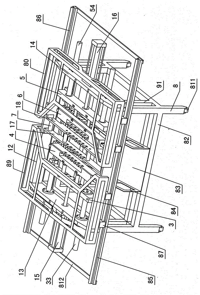
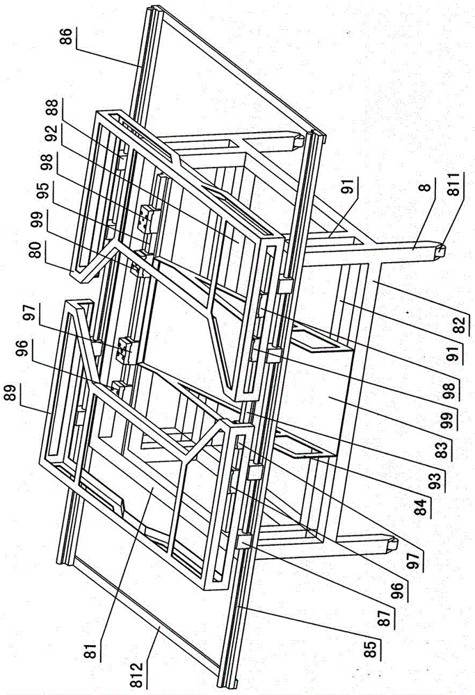
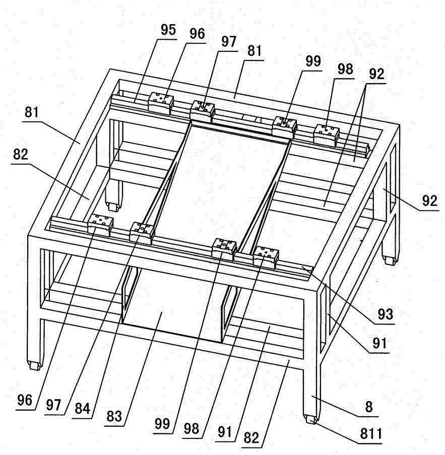
[0016] The invention relates to a core pulling machine for plastic electrofusion pipe fittings, such as figure 1 — Figure 9As shown, it is characterized in that it includes a fixed frame and a core-pulling mechanism. The fixed frame includes a support foot 8, an upper bracket 81 and a lower bracket 82 are formed on the support feet, and a front bracket is formed between the upper and lower brackets. Mounting frame 91 and rear mounting frame 92, front slideway 93 is installed on the front mounting frame, rear slideway 95 is installed on the rear mounting frame, the first left slide block 96, the second left slide block 97, the second left slide block 97, respectively are installed on the front and rear slideways. The first right slide block 98 and the second right slide block 99, a blanking hopper 83 is installed between the front slideway, the rear slideway and the lower support 82, the left and right sides of the blanking hopper are shaped on a fixed plate 84, and the fixed ...


PUM


Abstract

The invention relates to a core pulling machine for a plastic electric-fusing pipe. The core pulling machine comprises a fixed stander and a core pulling mechanism, wherein the fixed stander comprises support legs, wherein an upper bracket and a lower bracket are arranged on the support legs, front mounting frames and rear mounting frames are mounted between the upper bracket and the lower bracket, a front runner is mounted on the front mounting frames, a rear runner is mounted on the rear mounting frames, first and second left sliding blocks and first and second sliding blocks are respectively mounted on the front runner and the rear runner, a blanking hopper is mounted among the front runner, the rear runner and the lower bracket, a front sliding rail and a rear sliding rail are mounted on the upper bracket, front guiding blocks and rear guiding blocks are respectively arranged on the front sliding rail and the rear sliding rail, and a left protection cover and a right protection cover are respectively mounted on the front guiding blocks and the rear guiding blocks; the core pulling mechanism comprises a front mounting plate, a rear mounting plate, a left mounting plate and a right mounting plate, a left air cylinder and a rear air cylinder are respectively arranged on the left mounting plate and the right mounting plate, a left baffle and a right baffle are mounted between the front mounting plate and the rear mounting plate, left core pulling holes and right core pulling holes are respectively formed in the left baffle and the right baffle, a left connecting plate is mounted on the first left sliding block, a left connecting sleeve and a left connecting pin are arranged on the left connecting plate, a left clamping plate is mounted on the second left sliding block, a left clamping trough and a left core trough are formed in the left clamping plate, a left core support plate is clamped in the left clamping trough, a left core is inserted into the left core support plate, a right connecting plate is mounted on the first right sliding block, a right connecting sleeve and a right connecting pin are arranged on the right connecting plate, a right clamping trough and a right core trough are formed in the right clamping plate, a right core support plate is clamped in the right clamping trough, a right core is inserted into the right core support plate.

Description

technical field [0001] The invention relates to a machine for processing plastic electrofusion pipe fittings, in particular to a core pulling machine for plastic electrofusion pipe fittings. Background technique [0002] After plastic electrofusion pipe fittings are injection molded, due to their large tightness and resistance wires wound on the inner wall of the pipe fittings, the core and electrofusion pipe fittings must be taken out of the mold for cooling first, and then the core and electrofusion pipe fittings Put it on the core-pulling machine for core-pulling, which is beneficial to the core-pulling of electrofusion pipe fittings and guarantees product quality. Existing core-pulling machines for electrofusion pipe fittings, such as Chinese Patent No. ZL201220210318.9, the patent name is "a platform-type electrofusion pipe fitting core-pulling machine". The core-pulling mechanism of the patented core-pulling machine includes a frame, a platform desktop, The drive mech...

Claims


Application Information

Patent Timeline
Patent Type & Authority Applications(China)
IPC IPC(8): B29C45/33
CPCB29C45/33B29C45/332
Inventor 卢震宇金梅达谢细三牟亦龙陈小兵
Owner YONGGAO CO LTD
Why Eureka
Try Eureka