Circulating vertical-lifting elevator car and elevator system with same

A vertical lifting and elevator car technology, applied in the field of elevators, can solve the problems of poor comfort, low transportation efficiency, and low utilization rate of guide rails, and achieve the goals of improving comfort and safety, improving transportation efficiency, and shortening waiting time Effect

Active Publication Date: 2016-10-26
钟文沁
View PDF7 Cites 2 Cited by
  • Summary
  • Abstract
  • Description
  • Claims
  • Application Information

AI Technical Summary

Problems solved by technology

[0003] In the prior art, the elevator car can only reciprocate up and down along the vertical guide rails or approximately vertical guide rails, and cannot move left and right, which limits the elevator car between two rows of guide rails, making the utilization of the guide rails not high, especially The waiting time for elevators on high floors will be greatly extended, and the delivery efficiency will be low
In order to shorten the waiting time for elevators, the usual practice is to add guide rails and cars, such as large shopping malls and other public places with a large flow of people, but this will occupy more land and a larger building area, resulting in a waste of public resources
After the elevator runs under high load for a long time, the comfort of the car is often affected by external shocks, which makes it less comfortable. Regular maintenance is required. During the maintenance, one car and the corresponding guide rails are in a shutdown state, which not only reduces the transportation efficiency of the elevator, but also It also brings great inconvenience to people's travel
In addition, the car of the existing traction elevator is suspended on the traction rope, and there is a danger of the car falling due to the breakage of the traction rope

Method used


Image

  • Circulating vertical-lifting elevator car and elevator system with same
  • Circulating vertical-lifting elevator car and elevator system with same
  • Circulating vertical-lifting elevator car and elevator system with same

Examples


Embodiment Construction

[0026] Embodiments of the present invention will be described in detail below in conjunction with the accompanying drawings.

[0027] In the description of the present invention, the terms "central", "longitudinal", "transverse", "front", "rear", "left", "right", "vertical", "horizontal", "top", " The orientation or positional relationship indicated by "bottom", "inner", "outer", etc. is based on the orientation or positional relationship shown in the drawings, and is only for the convenience of describing the present invention and simplifying the description, rather than indicating or implying the referred device or element Must have a specific orientation, be constructed and operate in a specific orientation, and therefore should not be construed as limiting the scope of the invention.

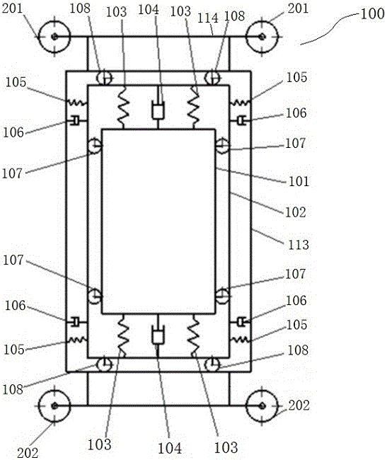
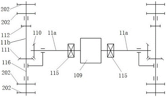
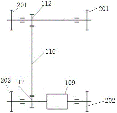
[0028] Such as Figures 1 to 4 As shown, the circular vertical elevator car 100 provided in this embodiment includes a passenger box 101, a support mechanism, a buffer mechanism, a travelin...


PUM


Abstract

The invention discloses a circulating vertical-lifting elevator car and an elevator system with the same; the circulating vertical-lifting elevator car comprises: a passenger car body; a supporting mechanism mounted outside the passenger car body for supporting the same; buffering mechanisms disposed between the passenger car body and the supporting mechanism for buffering external and internal impact that the passenger car body experiences; traveling sprockets disposed at the top and bottom of the passenger car body through the supporting mechanism for sliding the passenger car body along a rail an elevator shaft wall; and a driving mechanism in drive connection with the traveling sprockets. The circulating vertical-lifting elevator car provided herein enables simultaneous clockwise or anticlockwise cycling for multiple cars in corresponding rails, waiting time is shortened, and conveying efficiency is improved; all of the top, bottom and sides of the elevator car are fitted with buffering mechanisms to provide safety and comfort, and the elevator car is suitable for public places with heavy human traffic.

Description

technical field [0001] The invention relates to the technical field of elevators, in particular to a circulating vertical elevator car and an elevator system having the same. Background technique [0002] A vertical elevator has a car running between at least two vertical or inclination angles of less than 15° rigid guide rails. The vertical elevator is a tool for transporting passengers and goods up and down. The elevator car is the carrier for transporting passengers and is one of the decisive factors affecting the safety, comfort and transport efficiency of the elevator. [0003] In the prior art, the elevator car can only reciprocate up and down along the vertical guide rails or approximately vertical guide rails, and cannot move left and right, which limits the elevator car between two rows of guide rails, making the utilization of the guide rails not high, especially The waiting time for elevators on high floors will be greatly extended, and the transportation efficie...

Claims


Application Information

Patent Timeline
Patent Type & Authority Applications(China)
IPC IPC(8): B66B9/02B66B1/18B66B11/02
CPCB66B1/18B66B9/02B66B11/0273
Inventor 钟文沁
Owner 钟文沁
Why Eureka
Try Eureka