A kind of transformer nameplate installation method and transformer nameplate installation structure
A technology of installation structure and installation method, which is applied to transformer/inductor parts, instruments, display devices, etc., can solve the problems that the nameplate cannot be adjusted at will, many installation procedures, and it is inconvenient for users to view the content of the nameplate. The effect of wide versatility and easy production and processing
- Summary
- Abstract
- Description
- Claims
- Application Information
AI Technical Summary
Problems solved by technology
Method used
Image
Examples
Embodiment 1
[0030] This embodiment describes a method for installing a nameplate of a transformer. A connecting fitting is clamped at the upper or lower end of the transformer corrugated sheet; the front of the connecting fitting is blocked by the reinforcing rib connected to the transformer corrugated sheet to limit the forward movement of the connecting fitting; the connecting fitting is located on the transformer corrugated sheet. The parts on both sides of the sheet are respectively connected to the nameplate located in front of the transformer corrugated sheet, and the rearward movement of the connecting fitting and the nameplate is restricted by the transformer corrugated sheet blocking behind the nameplate, so that the connecting fitting and the nameplate are co-located and fixed.
[0031] Compared with the traditional transformer nameplate installation method, the transformer nameplate installation method of the present invention removes the restriction that the nameplate can only b...
Embodiment 2
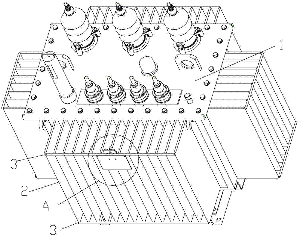
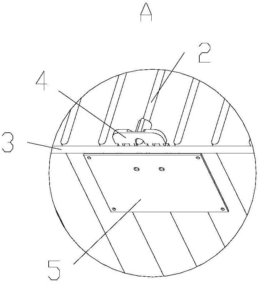
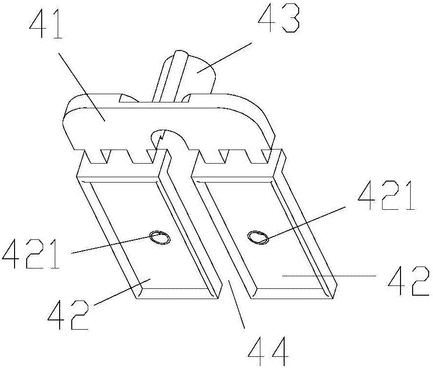
[0034] This embodiment describes a transformer nameplate installation structure, its structure is as follows Figure 1 to Figure 5 Shown; including connection fittings 4, nameplate 5 and transformer; transformer includes transformer body 1, several transformer corrugated sheets 2 longitudinally arranged outside the transformer body 1 and reinforcing ribs 3 connected to the front end of transformer corrugated sheet 2. The connection fitting 4 includes a connection block 41 and two installation blocks 42; the two installation blocks 42 are respectively arranged on the same side of the connection block 41; a distance is left between the two installation blocks 42 to form a clamping channel 44, so that the connection fittings It is clamped on the upper end of the transformer corrugated sheet 2; two mounting blocks 42 are respectively located in the gap between adjacent transformer corrugated sheets 2; the two mounting blocks 42 are respectively provided with mounting parts; the nam...
Embodiment 3
[0041] The difference between the installation structure of the transformer nameplate in this embodiment and the second embodiment is that: in this embodiment, the connecting fittings are clamped at the lower end of the transformer corrugated sheet; The upper end surface is fitted, and the mounting block can be supported on the upper end surface of the rib to achieve stable fixation. The height difference ΔH between the bottom of the positioning groove and the protruding surface of the mounting block matches the height difference between the lower end surface of the transformer corrugated sheet and the upper end surface of the reinforcing rib.
[0042] The rest of the structure of this embodiment is the same as that of the second embodiment.
PUM
 Abstract
Description
Claims
Application Information
 - R&D
- Intellectual Property
- Life Sciences
- Materials
- Tech Scout
- Unparalleled Data Quality
- Higher Quality Content
- 60% Fewer Hallucinations
Browse by: Latest US Patents, China's latest patents, Technical Efficacy Thesaurus, Application Domain, Technology Topic, Popular Technical Reports.
© 2025 PatSnap. All rights reserved.Legal|Privacy policy|Modern Slavery Act Transparency Statement|Sitemap|About US| Contact US: help@patsnap.com


