
A layered heat dissipation device for inner and outer winding coils

A technology of a heat dissipation device and coil, which is applied in the direction of transformers/inductors coils/winding/connecting, preventing/reduced electrical/magnetic effects, electrical components, etc., can solve problems without external coil heat dissipation, heat dissipation resistance and other problems , To achieve the effect of good heat dissipation, increase contact, and reducing the phenomenon of climbing

Active Publication Date: 2018-01-26
JIANG SU ZHONGRONG TECH
View PDF1 Cites 0 Cited by
  • Summary
  • Abstract
  • Description
  • Claims
  • Application Information

AI Technical Summary

Problems solved by technology

The insulation tube is simple and easy to operate, which improves the withstand voltage performance of the transformer; the structure of the insulation tube is simple, and it still has a certain effect on insulation, but the multi-layer design will bring more resistance to heat dissipation, and there is no specific External coil for heat dissipation

Method used


Image

  • A layered heat dissipation device for inner and outer winding coils
  • A layered heat dissipation device for inner and outer winding coils
  • A layered heat dissipation device for inner and outer winding coils

Examples


Embodiment Construction

[0025] The preferred technical solutions of the present invention will be described in detail below in conjunction with the accompanying drawings.

[0026] As shown in the figure, a layered cooling device for internal and external winding coils of the present invention includes a rolling device, an internal cooling device and an external cooling device;

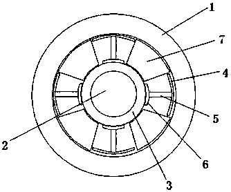
[0027] The rolling device is located between the high-voltage coil mechanism 1 and the low-voltage coil mechanism 2. The rolling device includes an inner cylinder 3, an insulating film is arranged on the inner surface of the high-voltage coil mechanism 1 and the outer surface of the low-voltage coil mechanism 2, and the low-voltage coil mechanism 2 is located Inside the inner cylinder 3, the inner cylinder 3 is made of insulating material, and four supporting parts are arranged on the outer surface of the inner cylinder 3, and the four supporting parts are equally divided on the outer surface of the inner cylinder 3, and the a...


PUM


Abstract

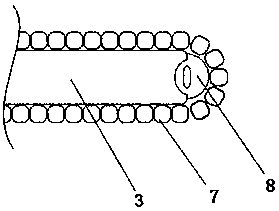
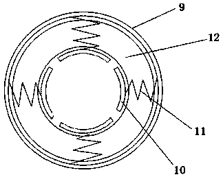
The invention discloses an inner and outer winding coil layered heat dissipation apparatus. The layered heat dissipation apparatus comprises a rolling apparatus, an inner heat dissipation apparatus and an outer heat dissipation apparatus, wherein the rolling apparatus comprises an inner cylinder; four supporting parts are arranged on the outer surface of the inner cylinder and adopt T-shaped structures; the inner heat dissipation apparatus comprises a heat dissipation strip mechanism; the heat dissipation strip mechanism adopts a chain structure formed by mutually hinging a plurality of heat dissipation blocks one by one; the outer heat dissipation apparatus comprises an outer cylinder; a plurality of coamings are arranged in the outer cylinder; and an annular cooling bag is arranged between the coamings and the inner surface of the outer cylinder. Compared with the prior art, the inner and outer winding coil layered heat dissipation apparatus has a relatively wide gap structure, so that the creepage between high and low level voltage coils is avoided; a rolling movement can be continuously performed in a formed gap by utilizing the heat dissipation strip mechanism to continuously take away inner heat; and a cooling liquid is added in the annular cooling bag of the outer heat dissipation apparatus to form water circulation so as to continuously take away heat on an outer high-voltage coil.

Description

technical field [0001] The invention relates to a coil heat dissipation cooling device, in particular to a layered heat dissipation device for inner and outer winding coils, which belongs to the field of electric equipment temperature control. Background technique [0002] All electromagnetic carriers of power transformers, such as iron cores, windings, leads, and structural parts that can be linked by leakage magnetic fields, are all heating elements. The heat generated by the heating element, in addition to increasing its own temperature, will also increase the temperature of the surrounding medium, especially when the local temperature is too high, it may cause premature damage to the insulation, or cause the insulation medium to age at high temperature for a long time. Gradually loses its insulating properties. As we all know, the life of the transformer is the life of the insulating material. When the transformer is required to have a certain life, the insulating mater...

Claims


Application Information

Patent Timeline
Patent Type & Authority Patents(China)
IPC IPC(8): H01F27/08H01F27/10H01F27/16H01F27/22H01F27/28H01F27/30H01F27/32H01F27/34
CPCH01F27/10H01F27/16H01F27/22H01F27/2876H01F27/306H01F27/325H01F27/34
Inventor 孙国平寻亚吴扣羊杨昆秦子恒
Owner JIANG SU ZHONGRONG TECH
Learn More