A sensorless brushless DC motor rotor commutation error correction method and control system

A brushed DC motor and error correction technology, applied in the direction of electronic commutation motor control, control system, electrical components, etc., can solve the problems of reducing motor efficiency, increasing motor torque ripple, etc., to improve commutation accuracy, reduce Effect of Error Convergence Time

Active Publication Date: 2018-06-08
BEIHANG UNIV
View PDF6 Cites 0 Cited by
  • Summary
  • Abstract
  • Description
  • Claims
  • Application Information

AI Technical Summary

Problems solved by technology

However, due to low-pass filtering, armature reaction and device delay, the opposite potential zero-crossing detection method will inevitably produce position detection errors, resulting in increased torque ripple of the motor, causing freewheeling of the non-conductive phase diode at high speeds, Generate negative electromagnetic torque and reduce motor efficiency

Method used


Image

  • A sensorless brushless DC motor rotor commutation error correction method and control system
  • A sensorless brushless DC motor rotor commutation error correction method and control system
  • A sensorless brushless DC motor rotor commutation error correction method and control system

Examples


Embodiment Construction

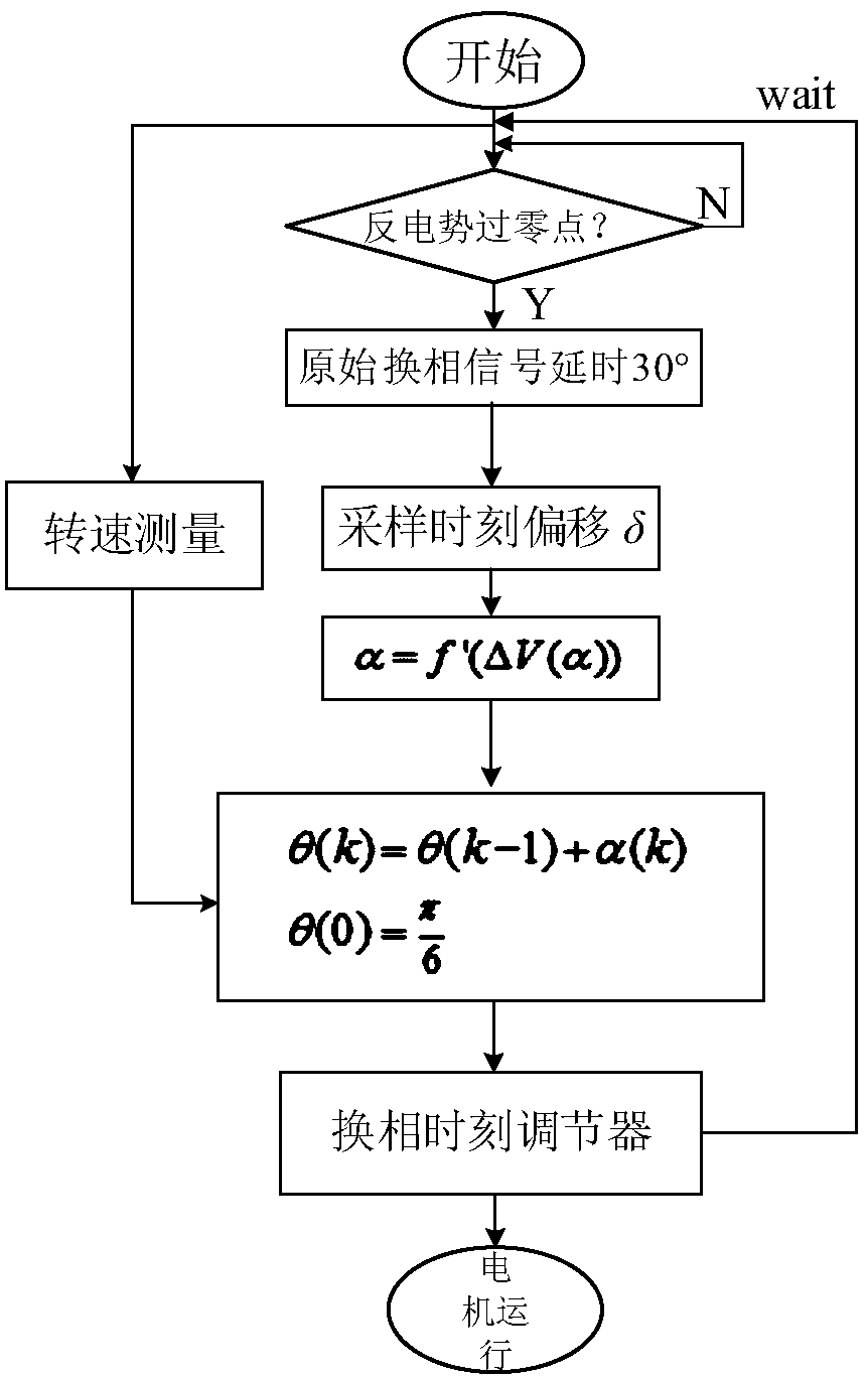
[0045] like figure 1 Shown, the method of the present invention realizes as follows:

[0046] In the first step, the system detects the rotor position according to the zero-crossing point of the back EMF of the non-conducting phase, and delays the zero-crossing point of the opposite electric potential by 30 electrical degrees according to the speed measurement information to generate the actual commutation signal.

[0047] In the second step, according to the error calculation method, the controller collects the voltage difference and calculates the commutation error from the error solution equation.

[0048] In the third step, the controller superimposes the appropriate compensation value into the commutation signal according to the commutation error, and then drives the motor to run.

[0049] In the fourth step, the control system repeats the first step to the third step to realize the closed-loop correction of the commutation error and drive the motor to run.

[0050] lik...


PUM


Abstract

The invention relates to a position sensor-free brushless direct-current motor rotor phase commutation error correction method and a position sensor-free brushless direct-current motor rotor phase commutation error correction control system. According to the position sensor-free brushless direct-current motor rotor phase commutation error correction method, opposite potential harmonic information of a motor is obtained through Fourier decomposition; an analytic relations between a motor-end voltage different value and a phase commutation point deviation phase when conduction begins and terminates and the phase of a phase commutation point deviates is analyzed; the phase commutation point deviation phase is obtained through backward reasoning based on the opposite potential harmonic information; and therefore, phase deviation which is calculated in real time is added to original signals, so that high-accuracy phase commutation signals can be obtained. According to the control system, based on the designed correction method, a closed-loop control mode is adopted, and therefore, the phase commutation error of the position sensor-free motor can be effectively reduced, and error convergence speed and the work efficiency of the position sensor-free motor can be greatly improved.

Description

technical field [0001] The invention relates to a method and a control system for correcting phase commutation error of a brushless DC motor rotor without a position sensor, which are used to realize accurate phase commutation of the rotor of a brushless DC motor without a position sensor. Background technique [0002] Brushless DC motors have the advantages of simple structure, convenient maintenance, high efficiency, good controllability, and excellent speed regulation performance, and are widely used in industrial fields. Traditional brushless DC motors use position sensors for rotor position detection and phase commutation. However, the installation of position sensors usually requires position alignment, adding additional leads, which affects system reliability, and the magnetic pins of military Hall elements will increase system power consumption. In order to avoid the above-mentioned unfavorable factors, the position sensorless motor drive technology is applied to th...

Claims


Application Information

Patent Timeline
Patent Type & Authority Patents(China)
IPC IPC(8): H02P6/182
CPCH02P6/182
Inventor 周新秀陈曦方敏
Owner BEIHANG UNIV
Why Eureka
Try Eureka