
Automatic conveyer for middle beam sheet metal part of kitchen cabinet

A technology for automatic conveying and sheet metal parts, applied in metal processing equipment, feeding devices, manufacturing tools, etc., can solve problems such as automatic positioning, automatic conveying difficulties, and the inability to realize continuous automatic production line processing

Inactive Publication Date: 2016-11-09
ANHUI KECHANG MACHINERY MFG
View PDF7 Cites 2 Cited by
  • Summary
  • Abstract
  • Description
  • Claims
  • Application Information

AI Technical Summary

Problems solved by technology

[0002] Kitchen cabinet center beam sheet metal parts are narrow, long and thin sheet metal parts. Automatic positioning and automatic transportation are relatively difficult. However, kitchen cabinet center beam sheet metal parts need to undergo multiple processing processes before they can become products. These multiple processing processes, such as punching , roll edge, end folding, side bending, etc. are all processed on different machines, and these mechanisms for realizing the processing process are generally set vertically on the processing route of the kitchen cabinet center beam sheet metal parts, and the kitchen cabinet center beam sheet metal However, the existing automatic conveying mechanism or manipulator cannot realize the fast, efficient, continuous and long-distance (>30m) automatic conveying and transshipment of narrow, long and thin sheet metal parts, resulting in the When processing the center beam sheet metal parts, it can only rely on semi-automatic intermittent processing, and cannot realize continuous automatic production line processing

Method used


Image

  • Automatic conveyer for middle beam sheet metal part of kitchen cabinet
  • Automatic conveyer for middle beam sheet metal part of kitchen cabinet
  • Automatic conveyer for middle beam sheet metal part of kitchen cabinet

Examples


Embodiment Construction

[0019] Embodiments of the present invention are described in detail below, examples of which are shown in the drawings, wherein the same or similar reference numerals designate the same or similar elements or elements having the same or similar functions throughout. The embodiments described below by referring to the figures are exemplary and are intended to explain the present invention and should not be construed as limiting the present invention.

[0020] In describing the present invention, it should be understood that the terms "center", "longitudinal", "transverse", "length", "width", "thickness", "upper", "lower", "front", " Orientation or position indicated by "back", "left", "right", "vertical", "horizontal", "top", "bottom", "inner", "outer", "clockwise", "counterclockwise", etc. The relationship is based on the orientation or positional relationship shown in the drawings, and is only for the convenience of describing the present invention and simplifying the descrip...


PUM


Abstract

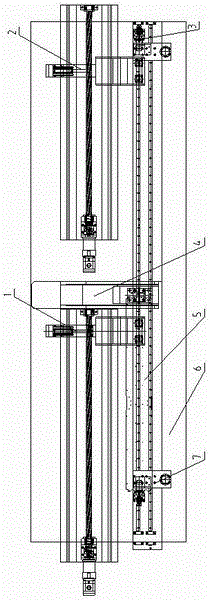
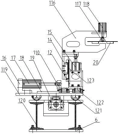
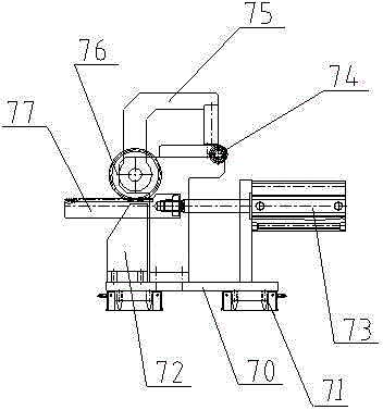
The invention discloses an automatic conveyer for a middle beam sheet metal part of a kitchen cabinet. The conveyer is composed of first, second, third and fourth mechanical arm assemblies, a base and length-direction brackets. The conveyer is characterized in that the structures of the first and second mechanical arm assemblies, which are same, are arranged on the base, and the mobile axes of the first and second mechanical arm assemblies in the length direction are located on a same straight line and is located on two sides of a processing mechanism; the structures of the third and fourth mechanical arm assemblies, which are same, are arranged on the base, and the mobile axes of the third and fourth mechanical arm assemblies in the length direction are located on a same straight line and length-direction brackets are arranged on two sides of the axes, respectively; and the mobile axes of the first and third mechanical arm assemblies are parallel. Compared with the prior art, the functions of fast automatic locating, automatic clamping, automatic conveying and the like of the middle beam sheet metal part of the kitchen cabinet are realized, and an automatic conveying action requirement with fastness, efficiency, continuity and long distance (longer than 30m) on a bending forming line of the sheet metal part of the kitchen cabinet is satisfied.

Description

technical field [0001] The invention relates to an automatic conveying mechanism, in particular to an automatic conveying mechanism for a middle beam sheet metal part of a kitchen cabinet. Background technique [0002] Kitchen cabinet center beam sheet metal parts are narrow, long and thin sheet metal parts. Automatic positioning and automatic transportation are relatively difficult. However, kitchen cabinet center beam sheet metal parts need to undergo multiple processing processes before they can become products. These multiple processing processes, such as punching , roll edge, end folding, side bending, etc. are all processed on different machines, and these mechanisms for realizing the processing process are generally set vertically on the processing route of the kitchen cabinet center beam sheet metal parts, and the kitchen cabinet center beam sheet metal However, the existing automatic conveying mechanism or manipulator cannot realize the fast, efficient, continuous a...

Claims


Application Information

Patent Timeline
IPC IPC(8): B21D43/10
CPCB21D43/105
Inventor 娄坤石成学梅志平孙素海
Owner ANHUI KECHANG MACHINERY MFG
Learn More