Electrohydraulic valve, outlet pressure control system and inlet pressure control system

A technology of inlet pressure and control system, applied in valve details, valve devices, safety valves, etc., can solve problems such as single valve function and achieve good stability

Active Publication Date: 2021-08-10
KC VAL SHANGHAI
View PDF10 Cites 0 Cited by
  • Summary
  • Abstract
  • Description
  • Claims
  • Application Information

AI Technical Summary

Problems solved by technology

[0003] The purpose of the present invention is to provide an electro-hydraulic valve, an outlet pressure control system and an inlet pressure control system to solve the defect of single valve function in the prior art

Method used


Image

  • Electrohydraulic valve, outlet pressure control system and inlet pressure control system
  • Electrohydraulic valve, outlet pressure control system and inlet pressure control system
  • Electrohydraulic valve, outlet pressure control system and inlet pressure control system

Examples


Embodiment Construction

[0090] The electro-hydraulic valve, the outlet pressure control system and the inlet pressure control system proposed by the present invention will be further described in detail below in conjunction with the accompanying drawings and specific examples. Advantages and features of the present invention will be apparent from the following description and claims. It should be noted that all the drawings are in very simplified form and use inaccurate scales, which are only used to facilitate and clearly illustrate the purpose of implementing the present invention.

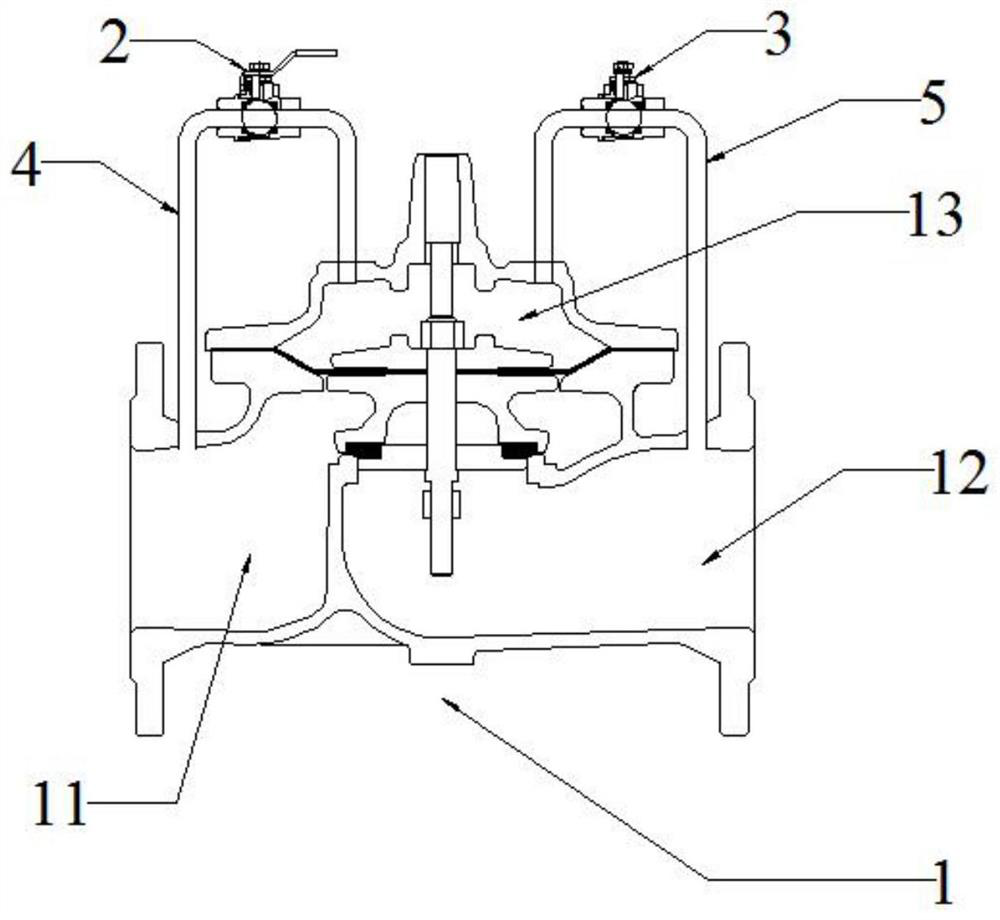
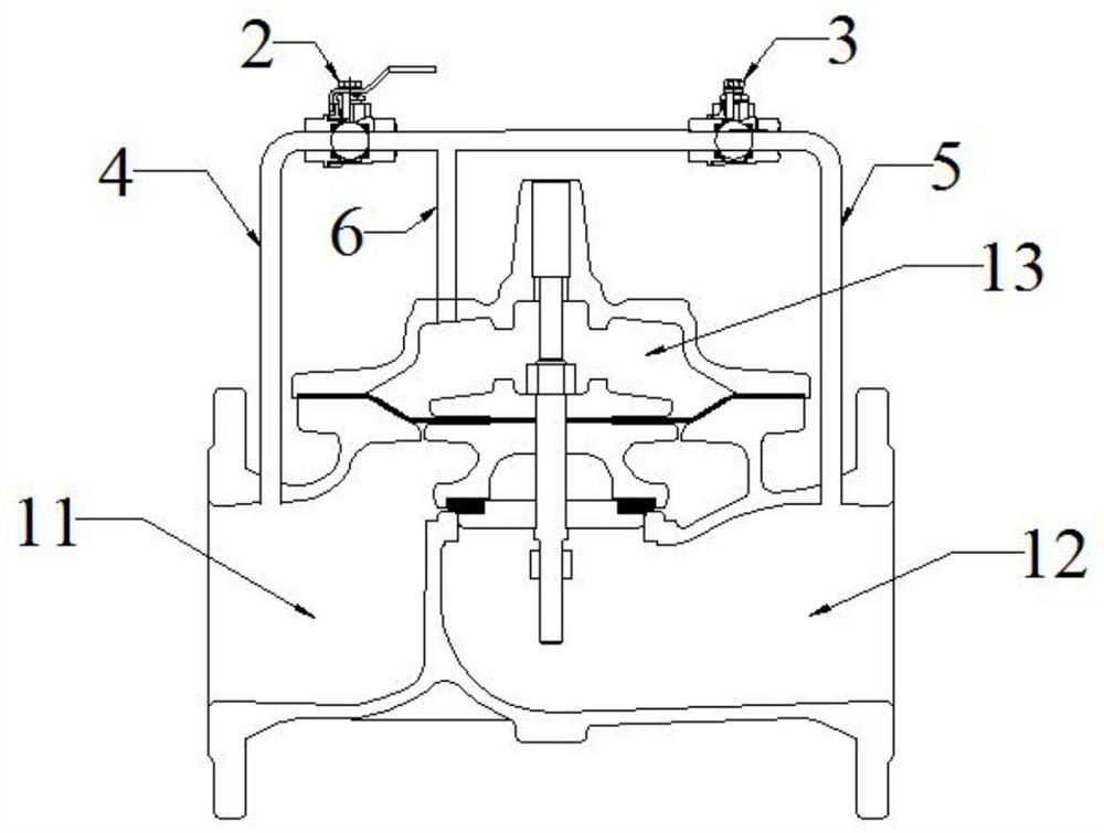
[0091] Such as figure 1 Shown is the structure of an electro-hydraulic valve provided by the present invention, which includes a main valve 1, a first control valve 2, and a second control valve 3;

[0092] The main valve 1 includes a main valve inlet port 11, a main valve outlet port 12 and a main valve upper chamber 13;

[0093] The inlet port 11 of the main valve communicates with the upper cavity 13 of the main v...


PUM


Abstract

The invention provides an electro-hydraulic valve, an outlet pressure control system and an inlet pressure control system. The electro-hydraulic valve includes a main valve, a first control valve and a second control valve; the main valve includes a main valve inlet, a main valve outlet port and the upper chamber of the main valve; the inlet port of the main valve communicates with the upper chamber of the main valve through a first conduit; the outlet port of the main valve communicates with the upper chamber of the main valve through a second conduit; the first control The valve is arranged on the first conduit near the inlet end of the main valve; the second control valve is arranged on the second conduit near the outlet end of the main valve. The electro-hydraulic valve provided by the present invention overcomes the shortcoming of a single valve function on the market, and can realize multiple functions in cooperation with different devices; moreover, the opening of the main valve valve can be adjusted within the range of 0-100%, and the stability is stable. it is good.

Description

technical field [0001] The invention relates to an electro-hydraulic valve, an outlet pressure control system and an inlet pressure control system, belonging to the field of valve control. Background technique [0002] In the general piping system of the prior art, traditional control valves generally can only achieve a single function, such as pressure reducing valves for decompression, pressure relief valves for pipeline protection, flow control valves for flow control or liquid level control. Controlled liquid level control valves, etc., when the pipeline system needs to achieve different functions, it is necessary to configure valves with different functions, or replace new and different valves, resulting in overly complicated pipeline systems, increased costs, and difficult maintenance. Contents of the invention [0003] The purpose of the present invention is to provide an electro-hydraulic valve, an outlet pressure control system and an inlet pressure control system...

Claims


Application Information

Patent Timeline
Patent Type & Authority Patents(China)
IPC IPC(8): F16K17/10F16K17/30F16K31/64F16K37/00
CPCF16K17/10F16K17/30F16K31/002F16K37/005
Inventor 杨晓军蒲昌烈章莹
Owner KC VAL SHANGHAI
Why Eureka
Try Eureka