
Fully distributed optical fiber strain and vibration sensing method and sensor

A vibration sensor and optical fiber strain technology, which is applied in the direction of converting sensor output, processing polarization reflectometer, testing optical fiber/optical waveguide equipment, etc., can solve difficult strain detection and other problems, achieve low overall cost, improve measurement function and application range , to reduce the effect of false positives

Inactive Publication Date: 2012-09-26
NANJING UNIV
View PDF5 Cites 0 Cited by
  • Summary
  • Abstract
  • Description
  • Claims
  • Application Information

AI Technical Summary

Problems solved by technology

However, since the strain on the optical fiber is not in a one-to-one correspondence with the change of the polarization state, and the POTDR technology mostly uses the method of comparing with the previous measurement to judge the state of the optical fiber, it is difficult for the POTDR technology to accurately measure the static strain and the larger strain. detection

Method used


Image

  • Fully distributed optical fiber strain and vibration sensing method and sensor
  • Fully distributed optical fiber strain and vibration sensing method and sensor
  • Fully distributed optical fiber strain and vibration sensing method and sensor

Examples


Embodiment Construction

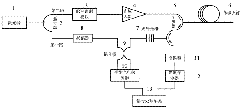
[0024] A fully distributed strain and vibration sensor structure such as figure 1 , the specific implementation steps of measuring strain and vibration are as follows:

[0025] 1) The continuous light output by the laser (1) is divided into two paths after passing through the first coupler (2);

[0026] 2) One of them is used as a reference light, which is connected to the first input end of the second coupler (9) after passing through the polarizer (8);

[0027] 3) The second path is modulated into pulsed light by the pulse modulation module (3), and then injected into the sensing fiber (6) as detection pulsed light through the circulator (5) after passing through the optical amplifier (4).

[0028] 4) The Rayleigh scattered light and Brillouin scattered light in the sensing fiber (6) are returned and emitted from the third port of the circulator (5).

[0029] 5) The fiber grating (7) transmits the Brillouin scattered light and reflects the Rayleigh scattered light....


PUM


Abstract

The invention discloses a fully distributed optical fiber strain and vibration sensor comprising a laser (1), a first coupler (2), a pulse modulation module (3), an optical amplifier (4), a circulator (5), a sensing optical fiber (6), a fiber bragg grating (7), a polarization scrambler, a second coupler, a balance photoelectric detector, an analyzer, a photoelectric detector (12) and a signal processing unit. Continuous light output by the laser (1) is split into two paths through the first coupler (2), wherein one path is used as reference light and is accessed to a first input end of the second coupler (9) through the polarization scrambler (8); and the second path is processed by the pulse modulation module (3) and the optical amplifier (4) and then used as detection pulse light to be injected into a first port of the circulator (5). In the invention, Brillouin optical time domain reflectometry (BOTDR) and polarization optical time domain reflectometry (POTDR) are simultaneously utilized for respectively and correspondingly carrying out fully distributed measurement on strain and vibration on a signal optical fiber, the defects of a system with single BOTDR or POTDR are overcome, and the false alarm rate or missed report rate of the system is decreased.

Description

technical field [0001] The invention is an optical fiber sensing device for fully distributed monitoring of strain and vibration, especially a combination of Brillouin Optical Time Domain Reflectometry (BOTDR) technology and Polarized Optical Time Domain Reflectometry (POTDR) technology that can simultaneously measure strain And fiber optic sensing equipment for fully distributed monitoring of vibration. Background technique [0002] When the optical fiber is affected by the external environment (such as temperature, pressure, vibration, etc.), the parameters such as the intensity, phase, frequency, and polarization state of the transmitted light in the optical fiber will change accordingly. By measuring these parameters of the transmitted light, it can be obtained Corresponding physical quantity, this technology is called fiber optic sensing technology. [0003] Distributed optical fiber sensing technology uses optical fiber as the sensing element, which can obtain the dis...

Claims


Application Information

Patent Timeline
Patent Type & Authority Patents(China)
IPC IPC(8): G01B11/16G01H9/00
CPCG01D5/35364G01D5/35303G01M11/3181G01L1/246
Inventor 王峰张旭苹王祥传
Owner NANJING UNIV
Learn More