Automatic drive test method

A test method and automatic driving technology, applied in the direction of using stable shear force to test the strength of materials, measuring devices, instruments, etc., can solve the problems of large disturbance of the clay to be tested, large error of test results, and inability to achieve horizontal positioning. , to avoid the large discreteness of test data, improve the applicability and reduce the disturbance of soil samples

Inactive Publication Date: 2016-11-09
CHINA NAT OFFSHORE OIL CORP +1
View PDF6 Cites 0 Cited by
  • Summary
  • Abstract
  • Description
  • Claims
  • Application Information

AI Technical Summary

Problems solved by technology

However, in the specific test process of the above-mentioned shear strength, the shear strength of the shallow soft clay cannot provide sufficient supporting reaction force for the test equipment of the conventional in-situ cross plate shear test; The plate shear test equipment cannot realize the shear strength measurement of the above shallow soil layer
[0004] Based on this, those skilled in the art also try to measure the above-mentioned soft clay with high water content in other ways; specifically, a certain column of clay to be tested is taken from the box sampler through a plastic tube, and the clay is limited by the wall of the plastic tube. To avoid large-scale flow, and then measure the shear strength of the above-mentioned clay to be tested in the plastic tube; the above-mentioned test process has the following disadvantages: the test is a manual point-by-point test, and only the peak value of the shear strength can be recorded. Continuous tracking test cannot be realized; the test is a vertical orientation test, horizontal positioning cannot be realized, and multi-point testing on the same plane cannot be realized, and the test result error is large; the string sampling operation of plastic pipe involves secondary sampling operation, and the clay to be tested The disturbance is large, which affects the accuracy of the final test result

Method used


Image

  • Automatic drive test method
  • Automatic drive test method
  • Automatic drive test method

Examples


Embodiment Construction

[0039] Embodiments of the present application will be described in detail below with reference to the accompanying drawings. It should be noted that, in the case of no conflict, the embodiments in the present application and the features in the embodiments can be combined arbitrarily with each other.

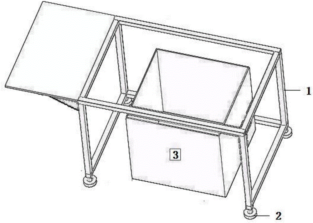
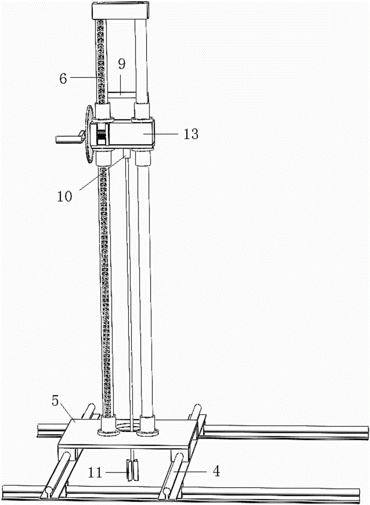
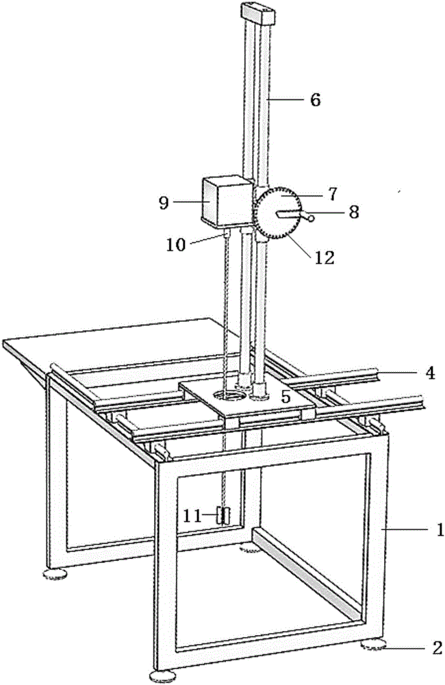
[0040] combine figure 1 , figure 2 as well as image 3 as shown,

[0041] The embodiment of the present invention provides an automatic driving test system, which can be provided with an equipment support 1, a driving mechanism, an automatic positioning mechanism, and a control mechanism; wherein, the equipment support 1 is provided with a cavity for accommodating the box sampler 3 to be tested, and the equipment The upper surface of the support 1 is set to place the positioning mechanism; the driving mechanism is arranged on the positioning mechanism, and the driving mechanism is provided with a cross plate test assembly, and the cross plate test assembly is set to be inser...


PUM


Abstract

This invention discloses an automatic drive test method, which comprises: a positioning operation, wherein the positioning operation comprises a horizontal positioning operation and a vertical positioning operation; a shear strength measurement operation, wherein the positive rotation starting of the drive motor of a drive mechanism is controlled by a control circuit, a cross plate test assembly is driven to rotate to preset the angle value, the torque value applied on the cross plate is real-timely collected through the control circuit during the rotation process and the corresponding rotation angle value is combined, and the curve map of the shear stress along with the rotation angle change is output and displayed; and after the peak value appears for 1 min in the curve map, the experiment is stopped and the peak value is determined as the shear strength value of the clay to be tested. According to the present invention, the automatic drive test method relates to, but is not limited to clay test equipment; and with the automatic drive test method, the drawbacks in the prior art can be effectively overcome, the shear strength test of the soft clay with the high water content can be achieved, and the precision of the final test result can be effectively ensured.

Description

technical field [0001] The present application relates to, but is not limited to, clay testing equipment, especially an automatic drive testing method. Background technique [0002] In the prior art, the cross plate shear test is a test for measuring the undrained shear strength and sensitivity of saturated soft cohesive soil with a cross plate, which belongs to the original test; It is inserted into the soft soil at the bottom of the hole and rotated at a uniform speed. Through a certain measuring system, the torque required for the rotation is measured until the soil is destroyed, so as to calculate the shear strength of the excavated soil. In the above specific test process, the cohesive soil to be tested needs to provide sufficient support and reaction force to ensure the smooth progress of the test. [0003] At present, in the marine deep-water environment, the shallow soil layer is weak clay with high water content, and the shear strength of this type of soil is an im...

Claims


Application Information

Patent Timeline
Patent Type & Authority Applications(China)
IPC IPC(8): G01N3/00G01N3/24
CPCG01N3/00G01N3/24G01N2203/0025
Inventor 周松望周杨锐蒋正波王建华郑喜耀王艳秋董明明刘双双王世龙陈磊
Owner CHINA NAT OFFSHORE OIL CORP
Why Eureka
Try Eureka