A vehicle self-drag scanning system for fixed transmission radiation imaging
A scanning system and radiation imaging technology, applied in the field of digital radiation scanning imaging, can solve the problems of complex structure, stable and reliable operation of the drag system affected by weight changes, and low inspection efficiency.
- Summary
- Abstract
- Description
- Claims
- Application Information
AI Technical Summary
Problems solved by technology
Method used
Image
Examples
Embodiment 1
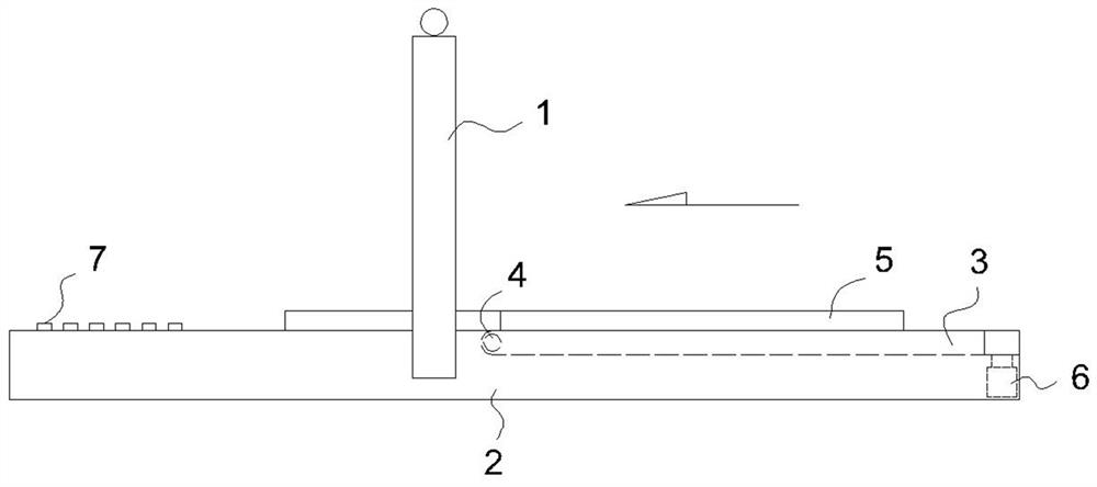
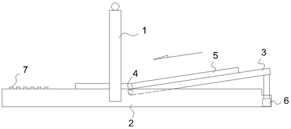
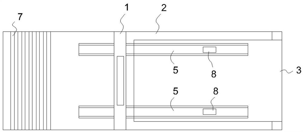
[0028] figure 1 , figure 2 , image 3 and Figure 4 The vehicle self-propelled scanning system for fixed transmission radiation imaging includes: a fixed transmission detection system, specifically, the fixed transmission detection system includes a frame-shaped scanning device 1 and an imaging device, and the scanning device 1 is fixed on the ground foundation 2, the vehicle passes through the scanning device 1, and a perspective image of the vehicle is formed on the imaging device.
[0029] On the vehicle entry side of the transmission detection system, more specifically, a ramp 3 is set on the vehicle entry side of the scanning device 1, the ramp 3 is movable, and the end of the ramp 3 close to the scanning device 1 passes through the hinge shaft 4 Hinged on the ground foundation 2, the opposite end of the ramp 3 can rotate up and down around the hinge shaft 4, thereby changing the inclination angle of the ramp 3 relative to the horizontal plane. A hydraulic cylinder 6 ...
Embodiment 2
[0035] Figure 5 The second embodiment of the present invention shown has basically the same structure as that of Embodiment 1, the difference is that the wheel track is a single-side wheel guide groove 5', and the single-side wheel guide groove 5' is only on the vehicle side. The guide groove is set under the side wheel, and the section structure of the guide rail groove 5' on one side wheel is referred to Figure 4 .
Embodiment 3
[0037] Figure 6 The third embodiment of the present invention shown is basically the same structure as Embodiment 1, except that the wheel track is a vehicle guide rail groove 5'', and the groove width of the vehicle guide rail groove 5'' is 1.2-2 times the width of the vehicle, the slot height ranges from 3cm-20cm, and its cross-sectional structure refers to Figure 4 .
PUM
| Property | Measurement | Unit |
|---|---|---|
| width | aaaaa | aaaaa |
| length | aaaaa | aaaaa |
Abstract
Description
Claims
Application Information
 - R&D
- Intellectual Property
- Life Sciences
- Materials
- Tech Scout
- Unparalleled Data Quality
- Higher Quality Content
- 60% Fewer Hallucinations
Browse by: Latest US Patents, China's latest patents, Technical Efficacy Thesaurus, Application Domain, Technology Topic, Popular Technical Reports.
© 2025 PatSnap. All rights reserved.Legal|Privacy policy|Modern Slavery Act Transparency Statement|Sitemap|About US| Contact US: help@patsnap.com


