Lifting hydraulic system of tubing string and using method of lifting hydraulic system

A hydraulic system and tubing string technology, applied in drilling pipe, casing, earthwork drilling and production, etc., can solve the problems of complicated control system, high installed power of lifting equipment, waste, etc., and achieve simple mechanical structure, energy saving, The effect of reducing production costs

Pending Publication Date: 2021-11-02
WUHAN MARINE MACHINERY PLANT
View PDF0 Cites 0 Cited by
  • Summary
  • Abstract
  • Description
  • Claims
  • Application Information

AI Technical Summary

Problems solved by technology

[0008] The purpose of the present invention is to overcome the shortcomings of the prior art that the installed power of the hoisting equipment is too large, there is waste during use, and the control system is complicated, and to provide a lifting hydraulic system with adjustable power and simple control system

Method used


Image

  • Lifting hydraulic system of tubing string and using method of lifting hydraulic system
  • Lifting hydraulic system of tubing string and using method of lifting hydraulic system
  • Lifting hydraulic system of tubing string and using method of lifting hydraulic system

Examples


Embodiment 1

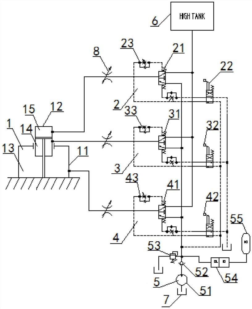
[0060] A lifting hydraulic system for an oil pipe string, the lifting hydraulic system includes: a combined hydraulic cylinder 1, a first hydraulic valve group 2, a second hydraulic valve group 3, a third hydraulic valve group 4, a hydraulic supply system 5, and a pressure oil tank 6 and the normal pressure oil tank 7; the combined hydraulic cylinder 1 includes a coaxial plunger cylinder 11 and a piston cylinder 12, the piston cylinder 12 is arranged inside the plunger cylinder 11, and the side wall of the piston cylinder 12 is connected to the column The piston cylinder port on the top of the plug cylinder 11 is slidingly fitted, and the piston cylinder 12 is in sealing fit with the plunger cylinder 11. The plunger cylinder 11 is provided with a plunger oil chamber 13, and the piston cylinder 12 is provided with a first oil chamber. chamber 14 and the second oil chamber 15, the oil outlet end of the first hydraulic valve group 2 communicates with the second oil chamber 15 prov...

Embodiment 2

[0070] Embodiment 2 is basically the same as Embodiment 1, and its difference is:

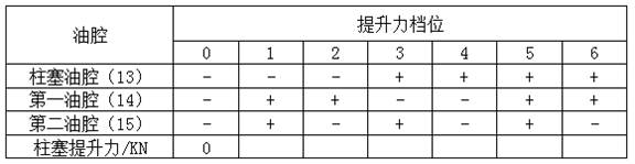
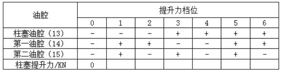
[0071] The second step: in the judging step, the lifting force gear of the lifting hydraulic system is shown in Table 1:

[0072] Table 1:

[0073]

Embodiment 3

[0075] Embodiment 3 is basically the same as Embodiment 2, and its difference is:

[0076] In the third lowering step, when the operator judges that the gravitational force on the tubing string is greater than the sum of the resistance provided by the plunger oil chamber 13 and the second oil chamber 15 and the lifting force provided by the first oil chamber 14 after work, the operator shall operate Personnel manually switch the gear position of the second manual reversing valve 32, so that the hydraulic oil enters the liquid control end of the second hydraulic control reversing valve 31 after passing through the oil inlet port and the working port of the second manual reversing valve 32, and the hydraulic oil enters The liquid control end of the second hydraulic control reversing valve 31 drives the second hydraulic control reversing valve 31 to reversing. The oil passage at the oil outlet is connected, and the hydraulic oil enters the first oil chamber 14. At this time, the ...


PUM


Abstract

The invention discloses a lifting hydraulic system and a using method thereof. The lifting hydraulic system comprises a combined hydraulic cylinder, a first hydraulic valve group, a second hydraulic valve group, a third hydraulic valve group, a hydraulic supply system, a pressure oil tank and a normal-pressure oil tank, wherein the combined hydraulic cylinder comprises a plunger cylinder and a piston cylinder which are coaxially arranged, a plunger oil cavity is formed in the plunger cylinder, a first oil cavity and a second oil cavity are formed in the piston cylinder, the oil outlet end of the first hydraulic valve group is communicated with the second oil cavity, the oil outlet end of the second hydraulic valve group is communicated with the first oil cavity; the oil outlet end of the third hydraulic valve grout is communicated with the plunger oil cavity, the oil inlet end of each hydraulic valve group is communicated with the oil outlet end of the hydraulic supply system, and the oil inlet end of the hydraulic supply system is arranged at the bottom of the normal-pressure oil tank. According to the design, the working power can be flexibly adjusted according to the weight of the tubing string, power waste is avoided, economical efficiency and environmental friendliness are effectively improved; and moreover, a control system is simple in mechanism and high in reliability.

Description

technical field [0001] The invention relates to a lifting hydraulic system, in particular to a lifting hydraulic system of an oil pipe string and a use method thereof, and is particularly suitable for a lifting hydraulic system with adjustable working power. Background technique [0002] In recent years, various countries have paid more and more attention to the development of energy, and the demand for various onshore petroleum energy equipment has also increased. Among them, the oil pipe is the pipeline that transports crude oil and natural gas from the oil and gas layer to the surface after the drilling is completed, and it is used to withstand the pressure generated during the production process. In oil field workover or pump overhaul operations, oil pipes and sucker rods need to be lifted out of the well one by one. After the operation is completed, the oil pipes and sucker rods are lowered into the oil well one by one. [0003] At present, the lifting and lowering of ...

Claims


Application Information

Patent Timeline
Patent Type & Authority Applications(China)
IPC IPC(8): F15B13/02F15B11/028F15B11/072F15B1/26E21B19/086E21B19/00
CPCF15B13/02F15B13/027F15B11/028F15B11/072F15B1/265E21B19/086E21B19/00F15B2211/3157
Inventor 刘利明周虎方敏刘杰阮长松
Owner WUHAN MARINE MACHINERY PLANT
Why Eureka
Try Eureka