Supercharge Your Innovation With Domain-Expert AI Agents!

A kind of touch screen scanning method

A scanning method and touch screen technology, applied in instruments, computing, electrical and digital data processing, etc., can solve the problems of long time consumption, low frame rate of touch screen, too many optical paths, etc. effect when

Active Publication Date: 2019-06-25
HUZHOU ZAAG ELECTRIC TECH
View PDF6 Cites 0 Cited by
  • Summary
  • Abstract
  • Description
  • Claims
  • Application Information

AI Technical Summary

Problems solved by technology

like Figure 1-2 As shown, the scanning method needs to determine the area where the logical touch point is located by scanning all the optical paths on both sides of the orthogonal, and then determine the position of the touch point by performing multi-angle oblique scanning on the area where the logical touch point is located. There are too many optical paths required to scan the point, which takes a long time, which makes the frame rate of the touch screen lower

Method used


Image

  • A kind of touch screen scanning method
  • A kind of touch screen scanning method
  • A kind of touch screen scanning method

Examples


Embodiment 1

[0042] Embodiment 1, a kind of touch screen scanning method, comprises the following steps:

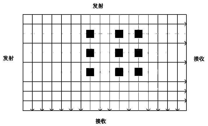
[0043] (1) Divide the full screen area of ​​the touch screen into regional blocks of a certain size, and set an area mask for each area block. The size of the divided area blocks can be set according to the specific required accuracy; set an optical path for each optical path Mask, the optical path mask of each optical path is the area mask or operation result of the area blocks that the optical path passes through.

[0044] (2) Determine the partition where the touch point is located:

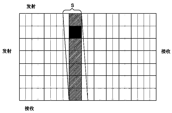
[0045] 2.1 Determine the first partition: scan all the optical paths perpendicular to one side of the touch screen, scan the area where the touch point is located in the scanning direction is the first partition, and the first partition is composed of several area blocks in the direction perpendicular to one side of the touch screen area strips, such as image 3 As shown by the whole vertical shaded...

Embodiment 2

[0052] Embodiment 2, a kind of touch screen scanning method, comprises the following steps:

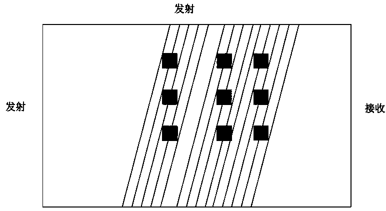
[0053] (1) Divide the full screen area of ​​the touch screen into regional blocks of a certain size, and set an area mask for each area block. The size of the divided area blocks can be set according to the specific required accuracy; all optical paths are layered, Each lightpath layer has a layer mask.

[0054]An optical path mask is set for each optical path, and the optical path mask has an area mask representing the area block that the optical path passes through, and a layer mask representing the optical path layer where the optical path is located.

[0055] (2) Determine the partition where the touch point is located:

[0056] 2.1 Determine the first partition: scan all the optical paths perpendicular to one side of the touch screen, scan the area where the touch point is located in the scanning direction is the first partition, and the first partition is composed of several ar...


PUM


Abstract

The invention discloses a touch screen scanning method, and belongs to the touch screen scanning technology. The method includes the following steps that 1, the whole-screen region of a touch screen is divided into region blocks of a certain size; 2, the partition where a touch point is located is determined, wherein the first step of determining a first partition and the second step of determining a second partition are carried out; 3, all light paths penetrating through the second partition are scanned to determine the touch point. According to the step 2, in the first step of determining the first partition, all light paths perpendicular to one side of the touch screen are scanned, the region where the scanned touch point is located in the scanning direction is the first partition, and the first partition is a region bar formed by a plurality of region blocks in the direction perpendicular to one side of the touch screen; in the second step of determining the second partition, light paths forming an inclination angle alpha with one side of the touch screen are scanned, the scanning range covers light paths penetrating through the region bar, and the region block where the touch point is located is determined as the second partition. By means of the method, the number of light paths needing to be scanned for recognizing the touch point is effectively reduced, so that time consumed for scanning the light paths is shortened, and the frame rate of the touch screen is increased.

Description

technical field [0001] The invention relates to touch screen scanning technology, in particular to a touch screen scanning method. Background technique [0002] At any point on the infrared touch multi-point touch screen, there are 2 or more light paths with different angles covering the touch area, so once there is an obstruction at this point, n light paths will intersect to form a point in this area. This is the basic theory of infrared multi-point recognition. [0003] A conventional infrared touch screen needs hundreds or even thousands of light paths to cover and superimpose all the touch areas. The larger the touch area, the more light paths are needed. After the touch screen scans all the light paths at one time, it is usually called a frame, and the scanning Each optical path takes a certain amount of time. The more optical paths, the longer it takes to scan a frame, and the lower the frame rate of the touch screen. The scanning time consumption of each optical pa...

Claims


Application Information

Patent Timeline
Patent Type & Authority Patents(China)
IPC IPC(8): G06F3/041G06F3/042
CPCG06F3/0412G06F3/0416G06F3/0421
Inventor 王迪李金鹏齐洋周建
Owner HUZHOU ZAAG ELECTRIC TECH
Features
  • R&D
  • Intellectual Property
  • Life Sciences
  • Materials
  • Tech Scout
  • Unparalleled Data Quality
  • Higher Quality Content
  • 60% Fewer Hallucinations
Learn More