Battery cover installation structure and terminal device

A technology for installation structure and terminal equipment, which is applied in the direction of battery cover/end cover, telephone structure, structural parts, etc. It can solve the problems of large gap between the terminal body and the battery cover, difficulty in dismounting the battery cover, and inconvenient use for users, so as to avoid Magnetic interference, enhance stability, realize the effect of installation and disassembly

Inactive Publication Date: 2016-11-09
BEIJING XIAOMI MOBILE SOFTWARE CO LTD
View PDF7 Cites 1 Cited by
  • Summary
  • Abstract
  • Description
  • Claims
  • Application Information

AI Technical Summary

Problems solved by technology

In this way, the gap between the terminal body and the battery cover may be too large because the buckle is not in place; or the battery cover is difficult to disassemble because of the tight buckle, which is inconvenient for users

Method used


Image

  • Battery cover installation structure and terminal device
  • Battery cover installation structure and terminal device
  • Battery cover installation structure and terminal device

Examples


Embodiment Construction

[0028] Reference will now be made in detail to the exemplary embodiments, examples of which are illustrated in the accompanying drawings. When the following description refers to the accompanying drawings, the same numerals in different drawings refer to the same or similar elements unless otherwise indicated. The implementations described in the following exemplary examples do not represent all implementations consistent with the present disclosure. Rather, they are merely examples of apparatuses and methods consistent with aspects of the present disclosure as recited in the appended claims.

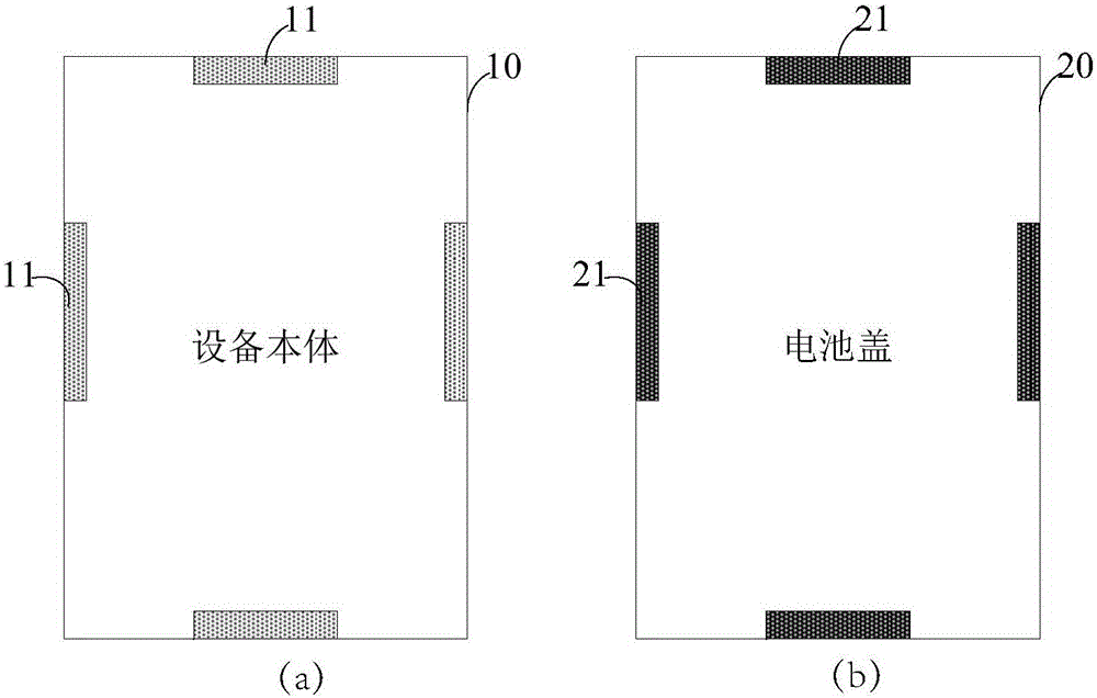
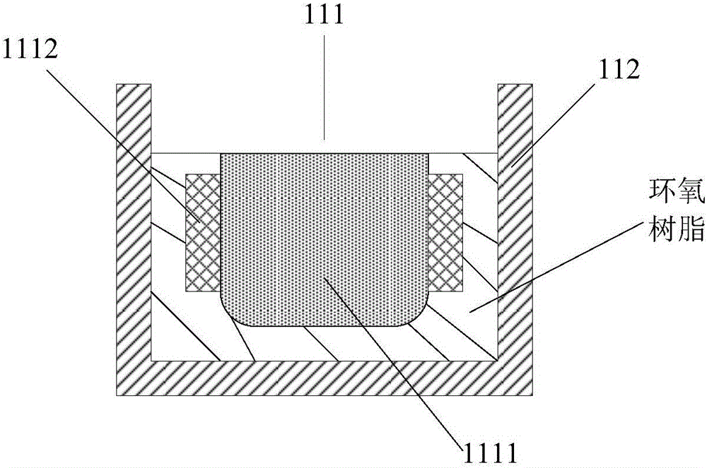
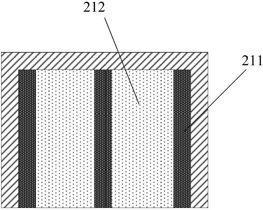
[0029] figure 1 a is a schematic structural view of a battery cover installation structure on the device body according to an exemplary embodiment, figure 1 b is a schematic structural view of a battery cover installation structure on the battery cover according to an exemplary embodiment. like figure 1 a and figure 1 As shown in b, the installation structure disclosed in this embo...


PUM


Abstract

The invention relates to a battery cover installation structure and a terminal device. The installation structure comprises a first magnetic pole and a second magnetic pole arranged corresponding to the first magnetic pole, wherein the first magnetic pole is arranged on a device body of the terminal device; the second magnetic pole is arranged on a battery cover of the terminal device; and the device body and the battery cover are connected through magnetic force of the first magnetic pole and the second magnetic pole. The uninstallation difficulty of the battery cover is lowered and the problem of an excessively large gap between the device body and the battery cover caused by improper fastening is avoided.

Description

technical field [0001] The present disclosure relates to the technical field of battery cover installation, in particular to a battery cover installation structure and a terminal device. Background technique [0002] The battery cover used in current mobile phone terminals and other equipment is basically a snap-on battery cover, and the fixed connection between the terminal body and the battery cover is realized through the snap structure on the battery cover and the lock structure on the terminal body. In this way, it is possible that the gap between the terminal body and the battery cover is too large because the buckle is not in place; or the battery cover is difficult to disassemble because of the tight buckle, which is inconvenient for users to use. Contents of the invention [0003] The present disclosure provides a battery cover installation structure and a terminal device, which are used to reduce the difficulty of disassembling the battery cover and avoid the pro...

Claims


Application Information

Patent Timeline
Patent Type & Authority Applications(China)
IPC IPC(8): H01M2/04H04M1/02
CPCH04M1/0262H01M50/147Y02E60/10
Inventor 冯振南常云波代建伟
Owner BEIJING XIAOMI MOBILE SOFTWARE CO LTD
Why Eureka
Try Eureka