Radiating module of cabinet

A heat dissipation module and chassis technology, which is applied in cooling/ventilation/heating transformation, instruments, electrical digital data processing, etc., can solve the problems of inconvenient operation, narrow equipment chassis space, etc., to reduce the operation time, simplify the replacement, and reduce the difficulty Effect

Inactive Publication Date: 2008-10-29
INVENTEC CORP
View PDF0 Cites 5 Cited by
  • Summary
  • Abstract
  • Description
  • Claims
  • Application Information

AI Technical Summary

Problems solved by technology

When the system fan or other equipment needs to be removed or replaced, the small chassis space filled with too many equipment often causes inconvenience in operation

Method used


Image

  • Radiating module of cabinet
  • Radiating module of cabinet
  • Radiating module of cabinet

Examples


Embodiment Construction

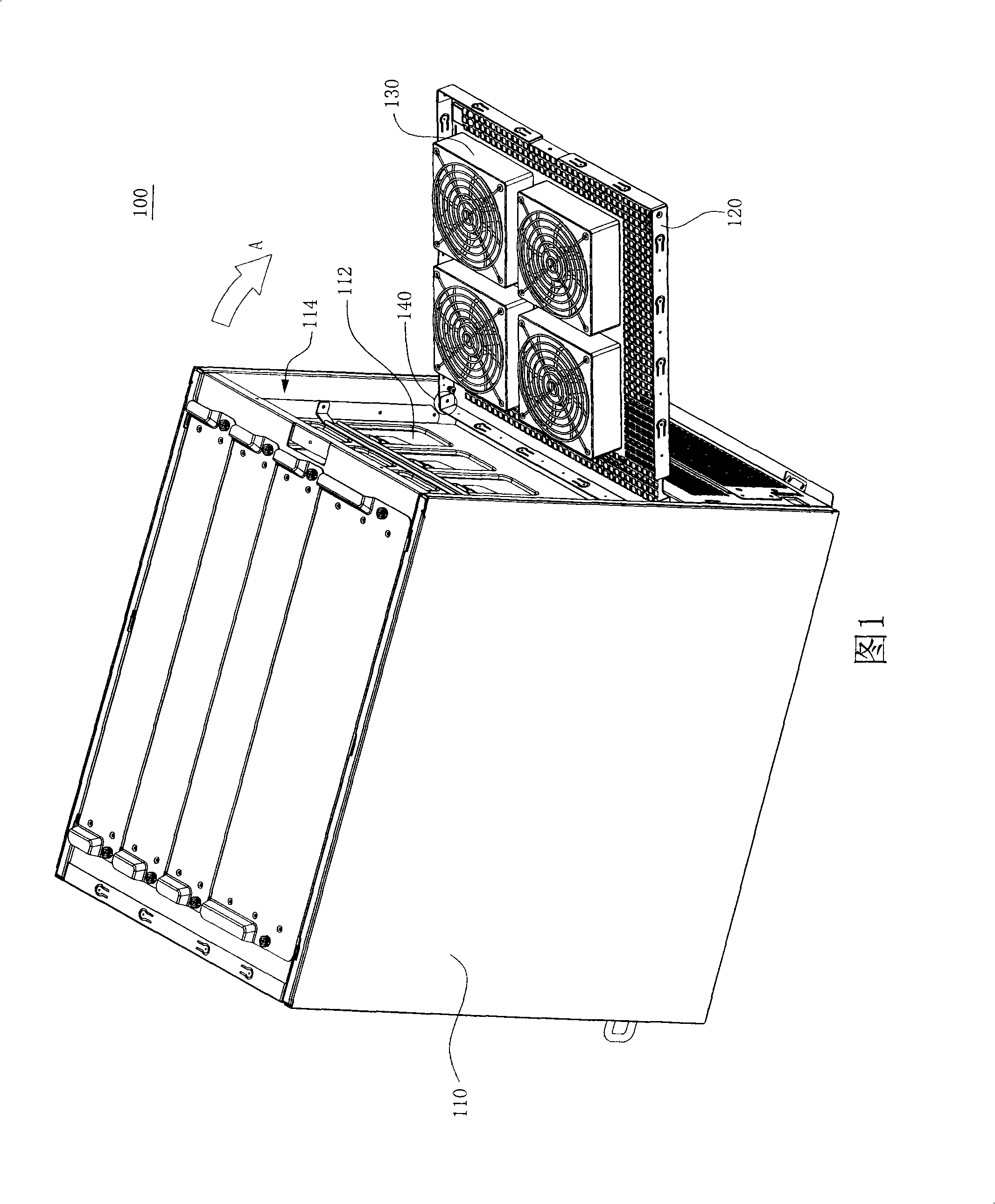
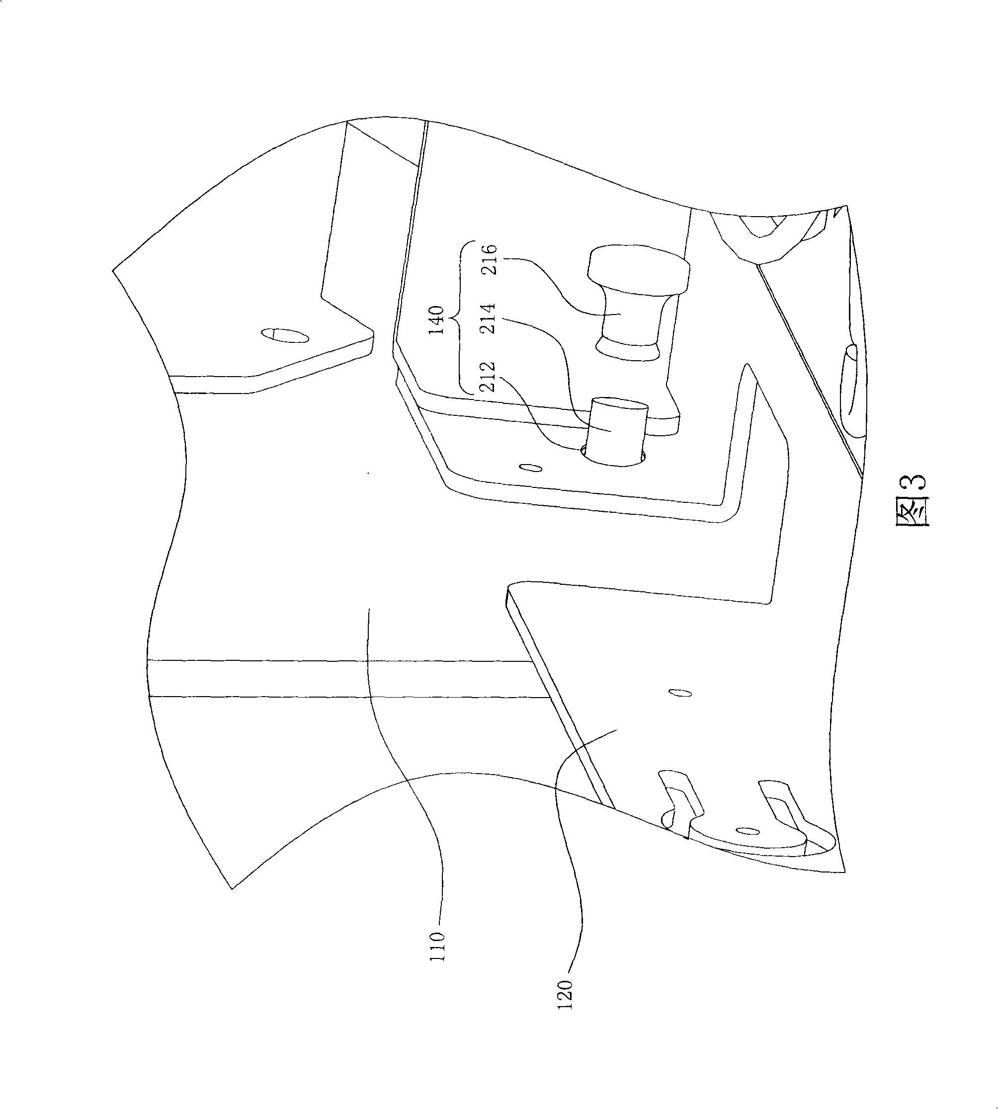
[0030] In the case cooling module of the embodiment of the present invention, the fan is fixed on the tray, and the tray and the case are coupled by a pivot structure, so that the tray can rotate toward the outside of the case, making it easier to disassemble the fan. Moreover, the tray can be completely detached from the chassis, which makes the replacement of the cooling module of the whole chassis easier. Anyone skilled in the art can change the number and types of fans and pivotal structures without departing from the spirit and scope of the present invention to meet various cost and application considerations.

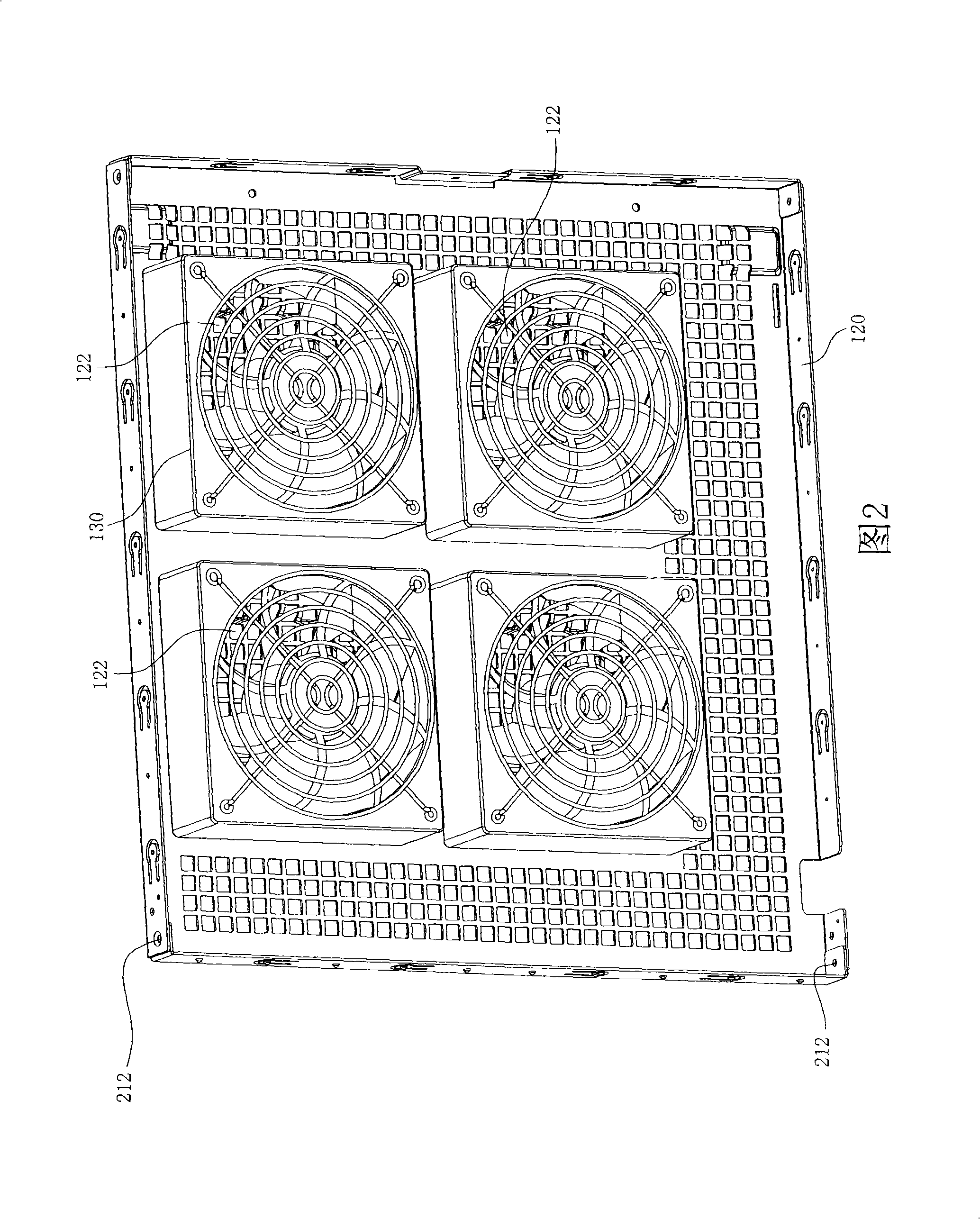
[0031] Please refer to Figure 1 and Figure 2 at the same time. FIG. 1 is a schematic diagram of a chassis cooling module 100 according to an embodiment of the present invention. FIG. 2 is a schematic diagram of the tray 120 and the fan 130 in the embodiment of the present invention. The chassis cooling module 100 has a chassis 110 , a tray 120 , a fan 130 and a ...


PUM


Abstract

The invention relates to a heat dissipation module of a case, which comprises the case, a pallet, at least one fan and at least one pin-jointing structure. The case is provided with an open face; the pallet is provided with at least one portiforium; the fan is fixed on the pallet corresponding to the portiforium and the open face. The pin-jointing structure is coupled with the case and the pallet, therefore, the pallet can turn towards the outer side of the case or the pallet can form the state of being parallel to the open face.

Description

technical field [0001] The invention relates to a heat dissipation module, and in particular to a case heat dissipation module. Background technique [0002] With the increase of the processing speed and the expansion of the functions of the computer device, the heat generated by each device inside the case becomes larger and larger. In order to remove the heat inside the chassis smoothly, the chassis is usually equipped with a cooling module to try to reduce the temperature of the entire system to maintain system stability. There are many types of heat dissipation modules. In order to meet the cost considerations, multiple system fans are generally installed on the inner wall of the chassis. The rotation of the system fans allows the air inside and outside the chassis to flow smoothly, reducing the system temperature. [0003] However, there are also many signal transmission lines, power lines and various adapter card devices inside the computer case. When the system fan ...

Claims


Application Information

Patent Timeline
Patent Type & Authority Applications(China)
IPC IPC(8): H05K7/20G06F1/20
Inventor 石逸群
Owner INVENTEC CORP
Why Eureka
Try Eureka